Joe realized the Left and Right Audio Channels were flipped, so that is a revision past the board I worked on and already posted. I opened up the SGB Console and swapped the Left and Right Audio Channels. Joe has updated the pcb designs on his Github project to reflect the change.
I quickly modeled a snug fitting plug to go into the hole that was for the 3.5mm jack of the Pi2/3. The first print was the same shape, but too lose, I made a size adjustment and reprinted it. The new one is very snug, I figure I will let it go and see if it gets loose over time. If so, I’ll put a bit of glue on it. It is resting there just above the pcb of the HDMI board so it has a little flat area on the bottom.
While I had it open, I also checked the fit of the new board for the back center screw post. It looks like I have it aligned and sized properly. That will mean that back screw post will not have to be cut out if the new board design is used. You still loose the front center screw, as the GameBoy Cartridge goes though that area. The level shifter ic in the area of that front center screw post is now “less” in the way, but it many need that post shaved down just a little still. Before the ic was resting on the edge of that post in the lower case, but now it should just be the pins and solder pads.
I looked at the Wii Controller port, I was looking if I could get a bit of plastic in to cover the front of the edge of the pcb at the top of the opening. This issue is because I used the Wii Breakout Board “with holes”. The 3d parts are designed for the smaller Wii breakout board Without Holes. You can try the Wii Breakout that doesn’t have the holes, it may fit better. I panelized the boards, so I got a huge amount of them, and for me the ones With Holes may be useful for another project at some point. There seemed to be two options to drop it all the way to the bottom of the opening, instead of raising it up from the bottom. Putting it all the way to the bottom didn’t work, it did give a bit of clearance on the top, but still not quite enough a gap in that tight area to reasonably get something to slip in from above. I then looked at raising it, the problem there is that the PCB and solder points on the back will be way to close to the upper main PCB. It may work in the short term that way, but overtime they may touch and short out. I thought of putting it so the pcb was turned downward. There just wouldn’t be any integrity in the 3d part, it would be way to thin I believe. The two posts that the top plate screws into could be removed to give clearance, or whatever is above the pcb may be possible to integrate into the top screw on piece instead. I’m concerned about how secure the jack would be mounted. I don’t think I will do anything else at this point about the mount. The way I did it, the jack is quite secure even if it has a 2mm gap above it. It is hard to see unless you get close and are directly in front of it. The Wireless Receiver for the controller also completely covers the area. I’d probably just suggest going with Joe’s smaller Wii breakout board, and use the models he provided unless you wanted to come up with a different mounting system of your own. I did use Joe’s lower mount plate model, and my jack fits right into that. For the Upper Screw on Plate, I am just using the upper most “flat” part of it, with the bits that would otherwise be hanging down cut away to fit properly. This presses the jack down tight by pressing down on the PCB side keeping it locked in very well.
I am finding it is slightly difficult to get the Gameboy Cartridge out. I am thinking if I had just left about 2mm more of the front case so the cartridge would be resting on it, that it would be a little easier to remove. The SGB cartridge slot is raised off the pcb by a few millimeters, and I have my opening closer to flush to the pcb. This angles the cartridge a little when I put pressure on to slide it out. I am just thinking if it had that bit of support on the end it may slide out slightly easier.
I also installed Joe’s updated firmware that uses the Home Button for the menu instead of Start + Select. On testing it I found an issue with the Color Scheme setting it would get stuck. Joe found and fixed that little bug and has released another firmware update on his Github page for the project.
For myself, I believe I am going to call this project finished now. The minor thing with the small gap above the Wii port isn’t a huge thing even to ocd me. The 3.5jack hole was an issue I wanted to resolve though. I was going to also close the SD Card slot. I decided not to as the 3d mounting plate behind it does reasonably prevent someone sticking something in there and it is a bit of ventilation. I have played several games of Tetris on it and last night I got to the final Boss in Super Mario Land. It seems to work well, it is fun, provided the game itself doesn’t get frustrating. Thanks for reading and have fun.
The only Vintage Game system or computer I have kept is my Game Boy DMG model. Based on the serial number I am guessing it was built in mid 1990. I had it from new and put a lot of hours on it playing games. It has seen better days. It was kept inside a case and never it an attic where it got hot. The case is pretty close to the original color, maybe some light yellowing. The display was missing lines, the glue failed on the screen cover and it fell off. I tried to glue the screen cover back on with super glue at some point, that held it on but ruined the “paint” on the under side of it.
The audio was being flakey on it at times. The screen even when it had the lines was well a DMG Screen.. I picked up some parts from Console 5 and somewhere else possibly on Ebay for my first pass of working on it.
So just as I said this was the “first pass” of parts that I purchased. Many of the items ended up not being in the Game Boy when I was finally finished. I broke the new Glass Screen cover, I did not use the replacement Volume pot, I did install most of the Cap Kit. The Button pads, were the wrong ones for the DMG. There also a back light kit with the Bivert board that I installed initially. Finally some Triwing drivers. It turns out my early Game Boy doesn’t have any Triwing Screws in it. It is all Philips screws. It isn’t in the picture, but as I had concerns about audio I did get a speaker as well, which I did not use.
It wasn’t too bad to clean up the old screen, you can see where the glue I had stuck it back on with years ago pulled the paint off the back of the plastic screen. I did have an issue with the new Glass Screen though.
Backlight and Bivert Mod:
So the first pass I went with the Backlight mod and the bivert board. The board was great. The removal of the old reflective layer was bad. Looking at the before picture, my screen wasn’t the best to start with.
Installing the board went very well following the provided instructions. There are 2 pins there to lift on the display connector on the CPU board side. The board is basically a carrier board for an inverter ic, the chip inverts the display. The light areas become dark and vice versa with it. With the Back Light rather than the reflective unlighted screen it makes it look better. The next part of the process was to take the reflective layer from the back of the LCD Screen. It was very tight, and while I got it off the lcd was missing more lines. I have seen people manage to repair the missing lines, but mine have been going bad since back when I was still using it in the 90s. Even so, it looked so much better with the backlight.
Original with my old clip on light.Back Light Mod with the bivert board
Yes it is missing more lines and even a couple horizontal lines now. Yes the Glass Screen broke installing it. The screen broke because it was very slightly oversized. I installed most of the capacitor kit, with the ones on the LCD, Power, and Audio boards. I tested the new ones and the old ones at the time on my component tester, none of them appeared to be bad. I left 5 of the 6 capacitors on the CPU board alone due to the other capacitors appearing to be fine, and due to being disappointed in the outcome of the screen, the glass cracking, and the fact that the audio issues didn’t clear up with the new capacitors.
Even in that condition the Game Boy was improved. I played it a bit like that. If the LCD wasn’t missing so many lines I would have kept it that way. It looked so much better and I wanted it keep it near original. That is why I didn’t go with one of the full LCD Replacements to start with.
On to a new LCD:
With the LCD not working properly though, I did end up getting one of the Replacement IPS LCD kits. The audio issue also ended up getting worse.
The instructions provided with the new LCD Kit worked out very well. This is an old project that I didn’t document much at the time. I did take a few before and after pictures. I would say the kits were fairly polished when I purchased mine, and they have been refined since.
The IPS Screen looks great, and has various color options to choose from. It doesn’t have the ghosting of the original lcd, which is a nice plus on fast moving games. The IPS Screen is the V2 or V3, which is now an older version of the screen, I am sure the V5s are nice these days. I put this in a few years ago now though.
Once the IPS Screen was installed the screen looked great minus the cracked glass cover. To fix that, I ordered another Glass cover, this one was also oversized, I filed it down with sandpaper on the edge to get it to fit. I also purchased a few more games for it to play with.
On to Sound Issues:
I was still having issues with the audio and it was getting worse. It would often not be working at power on, and then it may start working after a little while. With the audio getting worse I packed it up and let it sit in the case.
With Joes Super/Game Boy Console project catching my interest, I wanted to see if I could finally get my DMG back to full proper working order. Initially I thought maybe it was the audio jack. The Audio Jack has a switch built into it, when there are headphones plugged into the jack the internal speaker is disabled. I also wanted to look at the capacitors that were replaced and the ones that weren’t replaced. Looking at the Schematics for the CPU Board, the electrolytic caps are mostly audio related. Because I was working on the Super Game Boy Console, I let the DMG sitting in the case mostly. I wanted to add the Multiplayer Game Link function to the Super Game Boy Console, so I didn’t want to risk breaking the DMG before I could get that tested. I finished up the Super Game Boy Console recently (check my post about it if you are interested).
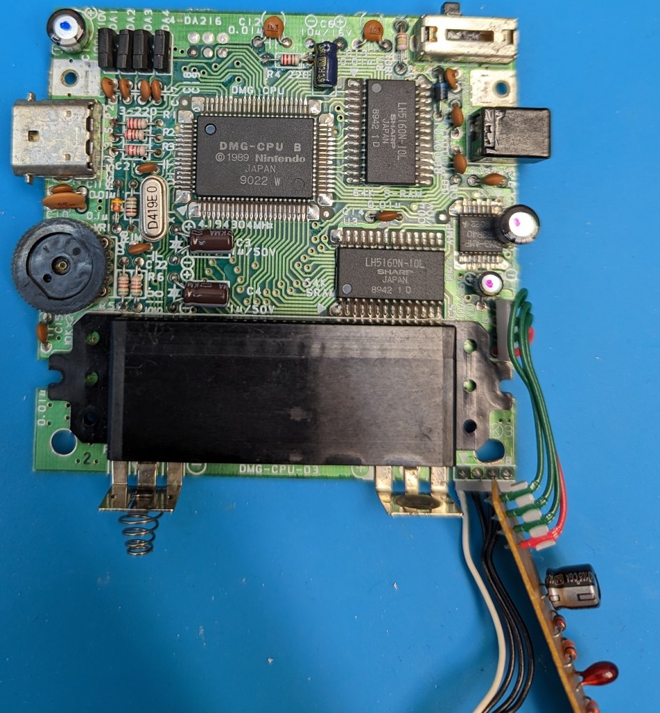
Last week after getting the SGB Console done and the Multiplayer tested I took a look at the DMG again. The audio is completely dead out of the speaker. I plugged in head phones and only had one channel of the audio and a lot of buzzing. I then took it apart, looking it over I didn’t see anything obviously wrong. The capacitors that were changed looked fine. I was able to tell that the CPU Board had 5 original capacitors still on it, as only one was replaced on it. The Audio Jack which was still a question for me has a lot of oxidation on all the exposed metal on it. I have seen other connectors do this at times. This socket has a switch in it that disables the audio. I had previously tried to clean it with contact cleaner but nothing changed.
Today I went to look at it further. I replaced the 5 remaining capacitors on the cpu board. I did test the capacitors I removed and the new ones before installation. With the tester I have for them, the old ones appeared to be fine. I did put quite a few hours on the Game Boy back in the 90s, but likely no where near used them for their rated hours at the temperatures the Game Boy runs at. I probably wouldn’t go to the trouble to replace the Capacitors on a DMG again anytime soon. Certain hardware from the later 90s has bad capacitors in them due to defective design or bad mix in the electrolyte etc. I also feel capacitors from the early 80s especially in equipment that gets quite warm, will have a greater chance of being in need of replacement. In some of my retro computers and other devices I have found capacitors that even my limited tester indicates are out of specification.
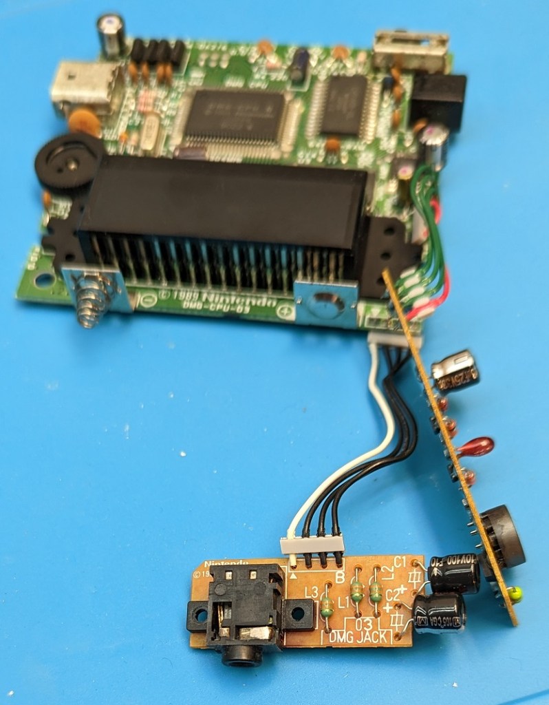
I looked over the boards again, but didn’t find any visible problems. I did clean up and redo some solder points, redid the power switch, the Link Port and some other solder points incase they had been stressed although I had not seen any visible cracked solder around any of the pins. I cleaned the tarnish off the exposed metal parts of the audio jack. I then removed the audio jack from the pcb with my desoldering gun. It shouldn’t have been awful to get off with the solder sucker. I tested it, and none of the pins were connected once it was pulled out. Checking the schematic, and tracing the wires I found that pin 6 of the audio amp is to be switched to ground, and that is the pin of the audio jack that goes to the white wire on the audio board. Testing again on the jack there was no continuity to the other half of the built in switch. I plugged in a 3.5 plug and it didn’t connect the switch. I was just able to see where the switch moved when the jack was inserted. I sprayed it with contact cleaner and used an Xacto blade to get a little under the switch. I was able to get the contact working again spraying it again and using the 3.5 plug in and out a number of times. I tested and had under 2 Ohms then. I also tested the 3 connections on the 3.5 plug and all are making good contact now. I then soldered the jack back onto the pcb and retested the switch and 3.5 plug contacts again.
Orange = Pin 6, Red to GroundSwitch Contacts in here..
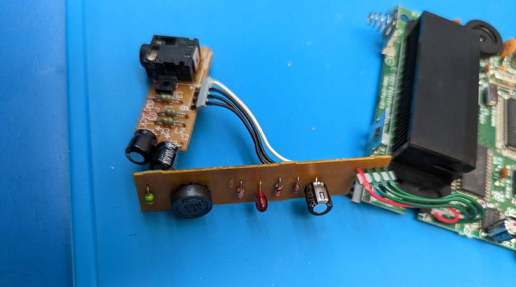
I have some other pictures of the boards before cleaning off the flux and reinstalling them. While I had them out, I put contact cleaner in the Multiplayer Link Port, the Volume pot, Power Jack and Power Switch.
The internal speaker worked properly again after reassembling the DMG. There is a bit of hum, but that is mostly from the AC Adapter, when on batteries there is nearly no hum. I don’t remember the hum being there in the 90s when using the same AC Adapter. In looking into the hum, it was reported that the IPS LCD kit adds some Hum to the audio, due to higher current draw, well that is what they said. Maybe it also is making some of it due to interference from it’s operation being picked up in the audio amp or something. It is not very bad, but certainly is more present when on the AC Adapter. It was worse actually before cleaning the power port, power switch and other contacts, I thought it was from the Audio Amp itself, but it was that same hum just worse before working on it this last time.
Reassembled and Testing:
The Directional Pad didn’t work properly though. While I had it apart, I had switched out the contact silicone pads, the Start, Select, A and B buttons all worked properly with the new pads. I took the DMG apart again and checked the pads. I cleaned the contacts on the PCB. I then tested conductivity of the new Directional Pad and also the Original Pad. The Original Pad was more conductive. I cleaned it lightly with IPA and reinstalled it. I also looked at them, and the new pad is designed just a bit differently. I tested the DMG again and the directional pad was working properly. I had swapped them as they are old and they look worn. It also seemed the directional pad wasn’t always working as well as I liked. It seems fine for after cleaning, hopefully it holds up.
The volume control is good and smooth, it isn’t scratchy at all. The power switch works properly making good contact, and the power jack is giving good connection too. The power cord could give some crackling before as it swiveled in the port on occasion before. It seems everything is finally working properly again. I’ll get a chance to play the old DMG again.
Looking at the photos from when I started working on the DMG, it has been over three years since I put in the Back Light mod and started putting the capacitors into it. It is nice having it finally sorted out and in good working condition again.
Trying a little Multiplayer Gaming:
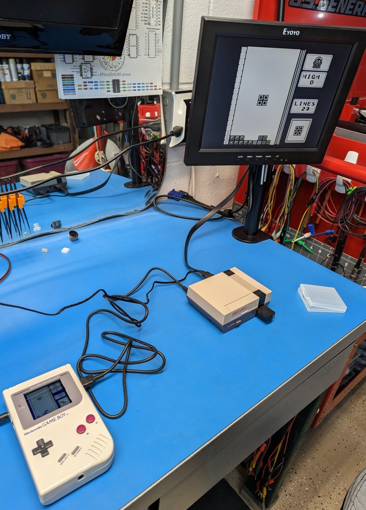
Now I can pair it up with my Super Game Boy Console and play some two player Game Boy games.
I was watching the Andy West’s video of Joe Ostrander’s Game Boy Console project on the Element 14 Youtube channel. It was inspired by and earlier project video that Andy West had done awhile ago. In the new video Andy builds one of Joe’s v3.0 boards, and gives some details I will likely be missing here.
The latest version from Joe was v3.1 it uses a Raspberry Pi Pico, a Super Game Boy Cartridge with a few other parts to build a Super Game Boy Console in a tiny Retroflag NESPi case. With v3.1 Joe used the Super Game Boy Cartridge Port instead of the SMD Cartridge Port Andy had for the v3.0.
Here is the Video:
I liked this project because it included some things I could practice with and some new things.
Andy’s original project included the DMG Link Port for Multiplayer games, but Joes project did not. I looked over the schematics for the SGB and the DMG as well as Joe’s version and it seemed simple to add that feature.
The Super Game Boy can play the original Game Boy DMG games. The Super Game Boy didn’t have the Game Link Port, but the CPU was the same except it doesn’t have the Nintendo name scrolling down the screen at power on (unless the cartridge isn’t recognized properly you never see that screen at all).
I was able to contact Joe and he sent me a copy of the Easy EDA Project files. He had it listed at v3.1 at the time with the Super Game Boy Cartridge port. I modified Joe’s main pcb to add in the parts required for the Link port. This was the first time I have worked with Easy EDA. It took me a little bit to get used to working with it. I have used Eagle in the past for other projects, but for Hobby work it is very limited in board size. Easy EDA can send an order to JLCPCB for production, or your can have it generate Gerber files to send to your favorite PCB Producer. I made a Footprint for the DMG Link Port is a recreation of Gekkio’s KiCad DMG Link Port KiCad footprint in Easy EDA, so that I could make the DMG Link Port adapter board.
There is a single Pi Pico that handles controller input and generates the VGA Video output. It also uses a VGA to HDMI Adapter to take the VGA output from the Pico to HDMI including the Audio.
It has options to either use a NES Controller port and Controller, or to take a Wii jack and use a compatible controller for that, be it one of the Wii Classic type controllers or one intended for the NES Mini such as I have used. There is different firmware for the Pico depending on which controller type you go with. Joe has both versions ready to go for you in the .u2f format. I went with the Wii port, and the cheapest way for me to get it quickly was to buy a Wii controller extension cable and salvage it out of there. I figured it was likely I could salvage and reuse it, and while 3 of the pins were cut short, it did turn out to be the regular through hole port and works just fine in my case. There are different Controller Port Mounts and as I said Firmware depending on which controller option you go with. The firmware is in the .uf2 format that is very easy to install to the Pico. You first download the .uf2 that you need on your computer, then get a usb cable for the Pico, hold the button on the Pico as you plug it into the USB port on your computer. You can release the button then, if you did it right, the Pico will show up as a drive on your computer. From there copy and paste the proper .uf2 file into that drive. The Pico will upload the code and reboot itself automatically. The files are gb_vga__pcbv3_nes_controller.uf2 for the NES Controller Port and gb_vga__pcbv3__nes_classic_or_wii.uf2 for the Wii Controller port (filenames prior to 1/15/23).
Update: 1/15/23 It appears Joe released an update for the code on the Pico, the new version only supports the Wii type controller. The Home button now brings up the OSD Controls. I’ll have to check it out later.
The Controller Ports also require different Adapter PCBs and wiring as well depending which you go with. The PCBs are labeled on both the Main PCB and the Breakout Boards. The pictures of my prototype board are not the final design for v3.21 on the final one (which I show a render picture of at the end of this post) you will find the “<– NES” and the “<– Wii” markings on the silk screen. Be sure to use 3V3 for the Wii Breakout. I have updated Joe’s Wii Breakout board to list 3V3 instead of VCC. For the NES use 5V and Gnd just as the board is labeled to accept.
Wii Controller Breakout BoardOriginal NES Break Out Board
There are numerous parts. Much of it is surface mount, minus the Pico and the reused SGB Cartridge port.
Wii Controller Breakout Board PCB (Optional this or the NES Breakout)
wii_jack_w_holes_v3_21
NES Controller Breakout Board PCB (Optional)
nes_breakout_v3
DMG Game Link Multiplayer Breakout PCB (Optional)
dmg_link_v3_21
USB Power with Data PCB (Optional, to Program the Pico in the case)
pcb_v3_usb_w_data
BOM
I used the USB Port from Retroflag instead of the optional “USB Power with Data PCB”, I don’t expect to need to reprogram the Pico that often. I ordered in Joe’s Wii controller PCB. I also ordered his Power and Reset button board. I ordered the version of the Main PCB that I had added in the Link Port parts. For the Link port I ordered in a DMG-07 Four Player adapter to salvage off one of the Link Ports as Joe suggested.
I have since created a somewhat more refined version of the Main PCB and some other PCB changes. Keep in mind the BOM list above is for the v3.21 board not the prototype I have pictures of here. Some component designations have changed and D1 is now a Diode Array on the “finished” board. I also created the DMG Link breakout board. I used the protoboard version as seen in the pictures, but the Mount for the DMG Link board is designed for the PCB.
The first part was to do the main PCB modifications. I ordered the required boards, I also found out you can have them panelize the boards for you. I now have a crazy number of Wii Controller Breakout boards for the same price I would have paid for 5. That opens up some real possibilities for when I have a small board I would like more of.
The next part of the project was sourcing all of the other parts. Joe’s BOM at the time had a mistake on it the 22pf capacitor listed was a 0201 imperial part. The BOM above is listing a 0603 imperial sized part. That is an easy mistake to make as 0201 imperial is 0603 metric.. The parts listed above are the specific part numbers I ordered except for the wire. If you don’t care to do the Link Port, then you don’t need R15-R18, D1-D5, or C5-C8, or the DMG Link PCB, and the Link Port itself.
Once I had all the required parts it was time to prep the various parts. For the Retroflag case, I had to desolder the USB power board from the Power Reset button board so I could reuse it. I then had to desolder the Power and Reset Buttons as well as the LED and the LED Light pipe so I could reuse them. I then installed the Power and Reset Buttons and attached the USB power board to the new PCB. Just a note I missed seeing the pad for the Resistor for the LED on the board, I revised the board so that was listed on the silk screen and installed a 510 Ohm resistor on it ( I expect a 1k resistor would do well too, if you don’t want it so bright).
The case requires a bit of modification to fit the new parts. The opening where the two USB ports needs enlarged depending on which Controller port type you go with. The top needs modified by cutting out the opening for the Cartridge to get in. That requires taking the front center post out of the top as well. Be careful to not remove too much. I did have to slightly trim some of the top posts (but not all) about the thickness of the PCB to get it to fit nicely. The back center post was removed on mine as well using the PCB as it was on the prototype. I revised the PCB so that v3.21 should let that back center post remain now. To see how much the top posts needed shaved down (about the thickness of the PCB) just check the fit of the PCB laying in the top of the case, it basically needs to sit level and about flush with it. For the Pi Pico to clear the top, I had to remove the tabs and a little bit more where the fan is to snap in. I think if the Pico is mounted with short posts it would have more clearance. I decided to mount it with some header sockets so I can remove it if I want/need to in the future. For the bottom there there is some material that needs removed from under where the green mounting part goes in for the Controller port. That part is where the Controller Port is mounted as well as the hole in it is the one hole that holds the VGA to HDMI board in place. Below you can see the modifications to the case. I didn’t think to take “before pictures”. You can also see the new Power Reset board, USB Power board as well as the Wii board mounted into the bottom of the case. The Link Port will be added to the lower right cavity later.
Beyond the case prep, and pulling those parts from the original Power Reset board there is the Super Game Boy Cartridge parts to deal with.
With the Super Game Boy, we pull the board. We need to salvage four parts. The CPU, the two Ram Chips (they are identical) and the Cartridge Port. Below you can see the board after those parts are removed. I did clean the flux from the board and kept it if I find a future use for it. To remove the chips I used the technique that Andy West showed with Low Temp Solder alloy. I watched him do it a couple times, I then watched some other people using it to remove chips. For me I wasn’t having all that great a luck with the CPU, so to make the process go easier I used my hot air station to make it easier that helped me a lot. It seemed that in Andy’s video it must have also taken him awhile to get the CPU off, I felt better using the hot air as the heat was applied for less time than it was taking with the iron alone. I am sure I would have gotten it with just the iron, but it is also nice to use the hot air station for more than heat shrink now and then. That low temp alloy is weird stuff, the flux smells odd too. It is the first I used it. Be sure to clean the low temp solder from the chips with some solder wick after removing them. It needs removed as it is not good to have it on the final board it doesn’t work as well as solder.
For the Cartridge Port, I used some money from Christmas to purchase one of the cheaper desoldering guns. I also used the new desoldering gun to remove the switches from the Power Reset board and VGA and Audio sockets from the VGA to HDMI adapter. I could have done it with my desoldering iron, it is shown in one of my C64 refurbishing posts. I also used it to pull the Link Port from the DMG-07 4 Player adapter.
Super Game Boy after removing the required ICs and Socket to be reused.
Below is the VGA to HDMI Adapter after it was prepped for installation. The VGA Port and the 3.5mm Audio port had to be removed. Even with the desoldering gun, I ended up pulling some of the through holes out of the VGA port, nothing that was a problem though in this case. It has 5V (Large Red), Ground (Large Green) for power that go over to the Power Reset board. Then the Dark Blue (Left Channel) and Brown (Right Channel) wires go to the pad for Left and Right audio over on the Main PCB, Ground is all joined so that doesn’t need a wire in this case. Then we have the Red, Green and Blue for the R, G, B pins then the Orange ( V Sync) and Yellow ( H Sync) and I did wire the Black wire for Ground there. The small wires are 30awg Wrapping Wire.
Below is the main work done on the unit. This was before adding in the Link Port.
Above you should be able to make out most if, not all the wiring there. I did put 2.5m screws into the Link Port holes to give it stability. You can possibly make out the green 3d printed washers under the screw heads. I didn’t want to scratch the pcb, and there is one trace right there by the left screw. The revised board has that trace relocated now away from the hole.
There is not too much going on on the top side of the PCB. The picture above was before I added the screws to secure the cartridge port. It is just the port and the Pico. I am using header sockets and pins so the Pico is removable if needed, but that shouldn’t be a big deal to solder it in with the normal pin headers. If you go to put it on header sockets, you may want to test fit it in the case to make sure it will fit. For me it got pretty close to having to cut out all that area where the fan is intended to be mounted.
To add the link port I modeled a part to sit down in the remaining cavity in the bottom corner of the case. I put the 3d printed link port mounting plate in for a test fit and I could not get it back out. Luckily my chip puller was able to get in under it and pop it out without damaging the case. The part is made so that you put the Game Link port in place and then press the 3d printed part in place, it clamps the port in by the little ears sticking back on it a bit. The main thing is to get the opening made in the right place at the right size for the port. I made a template of the port shape, then drilled a hole where it would be inside the area to help me get an idea on placement and got lucky enough I had it right in the end. I used a combination of small drill bits and an Xacto Knife.
I used two of the remaining shorter smaller diameter black screws from Retroflag to screw down the port PCB (or protoboard in my case). I didn’t expect the green printed part to fit in so securely, if it works loose I can just add a dab of glue and it shouldn’t be able to move. I do have all 4 sides fairly snug and the Link Port is put out into the case plastic so it can’t lift out on that side. I used Design Spark Mechanical to make that adapter mount, it was quite easy, far easier than getting something that dimension specific done in Tinker Cad. I have to spend more time using it. I probably could have made the Ampi case in it far more easily if I had stuck with it.
The image above is a view of the DMG Link Port Mount model. The first test print worked perfectly, which is uncommon. It was a snug press fit, the port fit right into the cavity for it, the screw posts printed solidly and the holes in it are the right size for the screws. You have to put the Link PCB with the jack on it while the mount plate it loose yet, just work them in together and you should have a good fit for both. It may look like the screw posts are back a bit far, but that is because my piece of proto board is a little shorter than the PCB I designed. I made the mount to match the PCB design, not the piece of proto board I am using.
Above is are renders of the DMG Link Port Breakout Board.
The unit is complete now and tested. I used it awhile without the Link Port as I was still sorting out some things on how I wanted to install it. I also had tested the Link function and it wasn’t working due to me not knowing that there is a twist in the cable, so two of the pins had needed switched with how I was connecting it up.
I have the revised v3.21 board shown above as it is now. Like I mentioned some component designations have been changed. D2 R18 etc. I have relocated some pads. I put the Wii pads together by bringing down the 3V3. The Work Ram is lower on the new revision. I think it may now clear the center front post in the lower case body, but with it where it is on my prototype it just gets in the way a little bit. I have added a notch in the board that should allow keeping the back center hole in the case instead of cutting the post off.
Joe has pulled my Fork into his project and corrected the Left/Right Audio being flipped as of 1/20/23.
Some may ask why make a Wedge case with Mechanical Keyboard with Full Size Ports for the Pi4b when there is the Pi400. I do like the Pi400 it certainly has it’s place. The AMPi4 was made for a bit different use case. I wanted a complete case with a mechanical keyboard, robust full size ports, a bit of weight to it, as well as SSD/NVME for storage and the OS.
If you look at my other posts here, you will see I like working with many of the 80s era computers. I never had an Amiga, and they are quite expensive these days. I also don’t want to dedicate more space for the storage of Retro Computers. I found after I started to get more and more Retro Computers around, that I am less and less likely to go to the effort of connecting one up and using it.
First I looked at the Pi400, which I thought may be a good option for Amiga emulation, and possibly more of the retro computers. The keyboard didn’t feel right, it was to small and too light so it easily to slides around the desk. The power adapter and other connectors are easy to accidentally pull out playing games etc. I also don’t like SD Cards for the OS as I have lost a few over the years in Pis. In many cases a Pi SD Card can quickly and easily be recreated or restore from a backup copy. For this setup, it takes a bit of work to get the OS just right, also it is to be a Living OS. I want to use it for Retro Computer Emulation, but I also want to use it for Linux with the GUI as a more modern option for basic usage and possibly some development work for various Microcontrollers and such.
I did also try Amiga Forever on my Windows pc, but it just doesn’t feel right on a wide screen LCD and Tower pc.
There are a number of Keyboard Wedge cases people have created for emulation systems. There are some for the Mister, which also I believe had a Pi option. I had seen some cases that take the Pi400 and wrap it into a larger case. I just did not find a case that was exactly what I was looking for. They were generally missing something I wanted in the system. They generally were a bit complex in design, with many parts and well they did have some style to them.
I expected I could come up with something that had all the features I wanted and be simple to print and build. It is a rather basic design. Mostly made to be easy to print, but certainly I am not that creative or very experienced in 3d modeling.
With that I looked at what I want in this setup: 1. Amiga Wedge inspired case. The initial case looked more like the Ti99/4a in profile until I narrowed the electronics compartment at the back.
2. Mechanical Keyboard
3. Full size HDMI Ports
4. Ethernet Port
5. USB Ports accessible, and more of them.
6. SATA SSD or NVME Drive
7. Internal Power Supply. This adds to it being simple to connect and adds weight to the system.
8. DE9 Ports for Joysticks (This doesn’t work quite right, I may yet get that sorted.. For now I have let that alone.)
Below is a view of the Second Revision of the case design that I printed. Some photos may be of the First Revision. There is a newer revision of the case with mostly small modification to adjust for some “mostly workable” but inconvenient items. I do plan to print that newest version of the case at some point. This part of the case is 300mm wide, so not every printer can print it. My S8 printer is 310×310, it seems that it is not possible to get the full 310mm though I got about 307mm with a correction to the alignment. That alignment issue had caused a mess with the First Revision print on the left side as it was trying to push the bed further than it actually could be moved.
Looking at the back panel, the far left hole is for the momentary Safe Shutdown Button that I put standard on just about any Pi project. It is the same type of setup as my Bartop Arcade machine. Next is the IEC AC Power port. After that is the Fuse. There is No Power Switch, I kind of would like one, but it was getting crowded. Then the 2 full size HDMI ports with the 30mm Fan beside them. RCA ports for the Composite Video and Audio output. Then a place for a standard Keystone jack, which I installed a RJ45 jack into for ethernet. Then a single USB Port. The far right side there just the place for the DE9 Joystick ports and the USB3 Hub ports and mounting posts for the screws. The Pi4 standoff screw points there in the middle of the case and holes for mounting the Meanwell 5Volt power supply.
To design the case I had to work out the parts I was going to use inside. I needed to make it big enough and get placement for all the parts. I created placeholders by measuring various components and making simple placeholders for them. Yes it would have been better to build the case in something other than Tinkercad. I would rather use something else, but that is all I had enough experience with at the time. The Keyboard Tray was started in Designspark Mechanical. I found I just wasn’t familiar enough with it, and it was slowing me down making it likely I would give up before finishing the project. I then went over to Tinkercad to design most of the case.
I already had two of the type of keyboard I chose, so I knew the how it was built. I was thinking initially to only design the electronics enclosure and attach the whole keyboard to the top of it. I decided to recreate the keyboard case “tray” instead. The keyboard tray/case is tapered a bit, making it problematic, the “feet” and “cord” openings were not optimal either.
Below is the original tray and my test print of the recreated tray. The Keyboard tray is two parts as it is well over 300mm wide maximum my largest printer can print. You can see I am at that point using the black keyboard instead of the white one. They are physically identical, just different plastic and paint colors.
Keyboard Parts
My first print print of the keyboard tray showed me the post positions were off and unusable. I adjusted for that and ended up with something closer. Even at being closer, the far left two posts are too far left by a little bit. Two others there are more slightly off. The smaller right side part was just about perfect for all posts, it was a second print as well. The posts were positioned based off of measurements, which wasn’t the easiest to get perfect. I think I did measure starting at the right side, so any variance was likely to get worse going further to the left side of the keyboard. I have since revised the position of those posts.
There is an issue in that the holes are to small and the posts tend to sheer off at the base. I carefully drilled the screw holes a bit larger after printing. I would revise the hole side on the 3d model, except it is in Tinkercad, and that’s really not practical in Tinkercad. That is why I wanted to use something else to make these models. If I had worked out using DesignSpark Mechanical or some other 3d design package it would have been an option to resize thoses holes after the fact. There is also variation in 3d printers, so you may find hole sizes are a bit different anyway, but likely not going to be large enough When it is together it is very solid. Not all of the posts are screw posts, some are just supports that don’t need holes at all.
Mounting Studs
The keyboard is mounted with brass inserts. These inserts are actually in the Top not bottom, but the screws come up from the bottom. They are very unlikely to ever pull out as they are pulled in tighter by the screws from the other side. Those are the four in the top of the keyboard that rest on those posts/pillars. The inserts in the keyboard tray here are actually salvaged out of old broken laptop cases. The 4 here in the upper area where the posts are did take longer screws I believe. I have a selection of Metric m2.5 screws of different length. There are also 4 more along the bottom edge of the keyboard as can be seen as holes without the inserts in them in the first keyboard photo. Those four lower ones are short screws.
Above is the original black keyboard when it was being installed.
Above you can see the various internal components test fit into the chassis. The USB Cable was modified already. The first revision the DE9 ports didn’t fit, the fan had an integrated grill that printed awfully and blocked to much of the fan.
Internals
Above most of the internal wiring is completed. The DE9 Joysticks ports are not yet wired to the GPIO and the Fan isn’t wired in yet. It is quite tight in there. The wires on the GPIO are going to the two LEDs on the top cover. Power and Activity lights.
Custom USB Cables and revised “corner”
Above is the second test print of the corner of the case as the DE9 ports didn’t fit and the USB Hub wasn’t properly positioned. The little black cable is the cable I made up for connecting the USB Hub. Due to the limited space those cables are made up with usb connectors without the shell covering them. The bottom cable there is the short keyboard usb cable, it plugs into the bottom of the keyboard where that square opening is in the keyboard tray.
More Internals
The 5V case fan is powered that little buck converter there between the power supply and HDMI port. The fan was louder than I liked, so I used the buck converter to lower the voltage a bit to make it quieter. You can see the 2.5″ SSD Drive is in the case. It also still has the 2gb Pi4 in it in this picture.
Early with 2.5″ driveLater with the NVME drive
The DE9 Joystick ports were very problematic. The first option for using them didn’t work at all, well it made my Power and Activity LEDs not work. The other options I tired required rewiring them to other GPIO pins. They were unreliable. It would have incorrect button presses as the timing must have been off for some reason. I was initially only going with Atari 2600 or the Commodore 64 3 button hybrid, but when those didn’t work I went with another option that was to have supported the Sega Genesis 6 Button controllers. I am not sure if the issues can be sorted. I have went to building and using a USB DaemonBite Retro Controller adapter setup for the Sega Genesis 6 button controllers. It even seemed to have faulty timing issues with the Genesis Controllers. I found a fix for that which seems to be working properly now. The DeamonBite adapter can be seen in the picture below. It is the more or less triangle shaped blue box to the right side with two DE9 ports on it. It is actually a simple build with an Arduino board controlling it. The case was available on Thingiverse. I want to go back to get those DE9 ports working off the GPIO. I have thought of putting an internally connected DeamonBite controller and wiring it to the case’s ports. That would loose me my USB2 port in the back though.
The system runs Raspbian and Retropie. I have it setup to boot into Retropie, but I can exit that and go into the GUI and use Raspbian. The main intention of this system is to run Retro Computer games. I worked to set it up primarily for Commodore 64, Atari 8bit, Ti 99/4a and Amiga emulation.
It was setup with at 2.5″ SSD Drive, and I ended up switching to an NVME drive later on. The keyboard was the cheapest version of the Redragon K552 87 key keyboard which was the Black version with Red Switches. I don’t like Red Switches. Once I was confident that the project was going to work out, I purchased the more expensive White version with the Brown Switches that I prefer.
The newest Revision 3 main case has various changes. Mostly small alignment changes. The Pi is moved to the left because the 3.5mm jack couldn’t fit with the outer plastic cover on it. I may not have moved it enough, I am not sure as the space is very limited and I have not reprinted it yet. Some other small adjustments to the back ports. I also changed the “vents” below the keyboard in the main frame as with the current shape they didn’t print very well.
I later found out that the key switches on the keyboard are removable. They aren’t quite “standard”, the contact pins on the bottom are smaller than standard switches. They probably won’t make contact in another keyboard. Standard switches won’t fit into the keyboard without filing the contacts down to be narrower like the ones that come in it. It is possible to do, I replaced several of the switches in my son’s keyboard as W A S D etc were worn and not working well. I will see if the Key Switches that Adafruit sells hold up better than the factory switches did.
Provided the prints are successful, the 4 printed parts take most of a 1kg spool of 3d printer filament.
There were various other supplies, M3 Brass Inserts for the top cover, some M2.5 Brass Inserts for the keyboard mounting. Various M3 and M2.5 screws of different lengths.
I have a Lenovo Tiny PC M600 Series that I wasn’t sure what to do with. It is a Pentium based CPU so not the best to use for very much. I have my Desktop PC on the other side of the room behind me when I am at my electronics bench. I’ve been wanting to put something over on the bench for awhile. I had various thoughts of using a Pi4 or something, but they are at such a premium right now I feel very doubtful I’ll get my hands on another one. They are not worth what they are currently selling for, if the Pentium Tiny doesn’t work out, I could buy an i5 Tiny for the same as the Pi4 these days.
Lenovo has made VESA Mount adapters for the Tiny, but I decided to check for a 3d printed mount design. I found a couple, but most were not what I was looking for. I picked one out that was close, but after taking measurements for some reason it was too narrow. All Lenovo Tiny’s I have had over the years have had the same dimensions.. So I find that odd.
I started over and came up with a one piece design that I liked, but it was a big waste of support material. I then came up with a two part design to save material and not need any supports. The first test print warped rather badly due to part of it coming loose from the bed part way through. It was good enough to test my dimensions, which needed some minor adjustments. I made a few other changes and printed it again, this time it stayed to the bed properly. The Tiny also fit it perfectly with the changes. I did make some one piece designs that take minimal support material as well. Since we had another model Lenovo tiny in the office, I decided to test fit that model. It does not fit due to the placement of the Feed on the case, I had added some material to stiffen the corners and feet for the second tiny are placed closer to the case edges. I figure I will modify the designs to accept either model before I call it finished.
Two Part MountThrough Hole for ScrewsTapered Screw Holes
Today I installed the M600 on my workbench with the Two Piece mount.
I came across a video on the GBS Control upgrade project for the GBS8200 boards. I had been interested in the GBS8200 back when I was doing my Commodore 128 RGBi/CGA to RGB video adapter. I had went with a SCART to HDMI adapter, as at the time that looked to be a better solution. It seems that device puts in a lot of delay though. It is useful to get “something” out of old RGB devices onto a HDMI compatible display, but when doing something like playing games the delay introduced is bad. I had not previously seen anything on the GBS Control project. The reason I had not used it at the time, was the SCART was to HDMI, where the GBS8200 outputs to VGA. The GBS8200 was a bit questionable too as it wasn’t super well liked in some circles at least.
There is now the GBS Control project, which involves wiring in an ESP board to take over control of the board. This greatly reduces the delay introduced in the output. It accepts input from 15kHz (or 31kHz) RGB/HV (VGA), RGBS (RGB Sync often wired with SCART or 4 RCA jacks) and YUB (Component) and outputs to regular 31kHz VGA. There are DAC nonbuffered based VGA to HDMI adapters that are available very cheaply as well that are said to not introduce additional lag.
It has various features beyond near no lag being introduced. It has Scan Line emulation, various resolution outputs, downscaling video from higher resolution to lower resolution output. The controls are all onboard the ESP web interface, which you can use by using the default broadcast it does, or link it to your wifi network. It also lets adjusting position, size and various other things with the output.
In my case, I went with a compact case that was based on the build instructions I followed from a video by Voultar that introduced me to the project. With the case I used I don’t have the RGBS input accessible which is wired to a SCART port. It does seem though RGBS input is an option into the 15pin VGA style port with Sync on the HSync pin. HV means Horizontal and Vertical Sync, where RGBS just uses a single Combined Sync or CSync signal. The case turned out great, it is a near perfect fit.
I made a few changes compared to Voultar’s instructions. First, I did not add the resistor to the Sync line for the RGBS, as with it that affects the RGBHV input from what I read, so if I did do it. I would want to wire up an input option to switch between it being in place and disabled. On going over what that is about, I believe it is to be there when devices use TTL Sync a 5V Sync Signal instead of the 1V max Sync that RGBHV generally uses. The next change I made was when soldering in the ESP board I used angled header pins for the two ground connections, that provides a much sturdier connection between the two boards than a piece of copper wire or solder only. In most cases either just solder, or at least using a bit of wire will likely be just fine though. I like that if it gets dropped the pin headers will be a lot sturdier. I also connected the power for the frequency generator to a different capacitor, Voultar had misspoken what the polarity was in his video while wiring up the power, that let me wondering if he was wiring it correctly or not. I decided to then go with how the project instructions at gitub showed it wired in. Voultar’s wiring was a little shorter for the power, but it was also a little harder to get in at it with the soldering iron. For all of the power wiring I used heavier wire, and for the various other low power wiring I used solid core 30awg wrapping wire. I found that I had issues with the solder points on the two chips with the adjacent pins getting bridged, and had used some desoldering braid to get rid of the bridges. More flux would have likely helped me avoid bridging the pins. Voultar has certainly done that kind of thing far more than I have. Thankfully there are only 4 solder points to various chip legs. The capacitors were easier to stack than I expected and they turned out very well.
Mostly I want it to use the GBS Control with my RGBI to RGBS or RGB/HV converter project I posted previously for the Commodore 128 80 column RGBI (CGA) mode.
I want to make a 5V output port for the VGA to HDMI DAC adapter at some point. I may do an audio passthrough option going in the front and out the back to connect into the adapter as well. I had thought of a power switch, but I use power strips for my equipment and generally turn them off when not in use. I have thought of a power LED as well, but still not sure on that one either. There was a version of the case that included putting the VGA to HDMI DAC adapter in the case. That was setup to remove the VGA output though, which I didn’t like. I have a number of VGA monitors I like to use from time to time.
For my first test of the unit, I connected it to the VGA output of a laptop. It passed through the VGA signal to the VGA output just fine. I then connected my Commodore 128 and my Digital RGBI to Analog RGBS / RGB/HV adapter. I built that adapter with the GBS8200 board in mind, so while it is setup it as RGBS + Audio through to the SCART connector I have configuration jumpers on the board. I changed the jumpers to NOT put 5V to the one pin which was to be the SCART mode detection. I also changed the Audio to not go to the HD15/VGA type connector and instead go to the RCA jack on the side. I changed the jumper to RGB/HV mode where it bypasses the Sync combiner circuitry on my adapter and outputs H Sync and V Sync. When connecting it up it worked great, I just adjusted some settings in the web interface to see how that worked out. The Scan Lines look pretty nice on it. I did not have any 80 Column mode programs prepared to use on the Commodore 128 to check it out too much at this time though.
This GBS Control is a baseline model build, more or less, for a bit more complex build check out the newer post linked below when I built a new unit and upgraded the one above to the new specification.
I have built another GBS Control and updated this GBS Control with some more connector options and features.
I figured I would make a post on the TI 99/4a I picked up awhile back. It was one of my first computers. I didn’t think of it at the time as a “real” computer though. I don’t even remember when I got it, but it was older and not current at the time, probably the early 90s. I wanted to get one and tinker with it like I have been with the other old systems from the 80s.
Really I am not sure I would recommend it yet. The system is so limited, I hate to invest in it. With a Commodore 64, short of a drive solution to get to and save data the Commodore 64 is complete. With the Ti if I want to do anything interesting, it seems I have to get a 32k ram expansion for it. That or stick to Basic and original cartridges. Many of the cartridges made now look like they require the 32k Expansion to operate as well.
Anyways I did get it, and I picked up some cartridges and even a tape player that I will look at in the future.
I did check the system out when I got it and took it apart. Inside it looked pretty good. The keyboard doesn’t work properly, it is one of the membrane types.. I am afraid also if I want to do much I will have to find a donor keyboard for it.
I did buy capacitors for it, there weren’t many.
Power Supply CapacitorsCapacitors for the Mainboard. A few spares as well.
Initially I wasn’t going to get out my desoldering iron, but I quickly changed my mind before even getting the first capacitor out. I use an ECG J-045-DS desoldering iron. It is a rather cheap device, but it has done very well for me. I do keep thinking about and looking at those fancier units like you see so much of on Youtube. The ECG is a quarter of the cost of even the cheapest of those though and has done well for me so far. I don’t get it out much, mostly it takes awhile to get heated up and does take two hands to operate.
First was the power supply, with 6 capacitors. I cleaned the power switch with some Tuner Contact cleaner while I had it open, initially I wasn’t sure if it was making nice clean contact. I also replaced the LED as it was so dim that it was hard to see. The original LED had longer legs than typical, so I extended them with a piece of solid copper wire and then put heat shrink to insulate the legs. The original LED also had some heat shrink on the negative leg. I tested the power supply and it worked properly afterward, and the LED was much brighter, but not too bright. I also tested with the 99/4a board attached and it all worked fine. The voltages tested good as well.
BeforeI did add the zip tie to the largest capacitor after the picture was taken, although it was quite secure already.Have to crack open the board. Two holding clip things and three bolts to remove this shield.
Then was the mainboard. That has 9 total. There is a single 10uF 35V, there are five 22uF 25V, and finally three 100uF 16V. To replace them I did get the five axial 22uF caps, but the 100uF I could only get in radial from the supplier I choose. The 10uF I couldn’t get an axial cap either so I went with a Tantalum instead, I could have picked up a radial 10uF though instead. When I did the Timex Sinclair 1000 I ended up getting some Tantalums for it as well.
Here is the board before. The Heatsink compound on the video chip there is replaced as well.The board after installing the new CapsAll of the new Capacitors.
The worst thing of switching out from the radial capacitors was making sure I had the new ones installed correctly. Even the Tantalum is a polarized capacitor. The Tantalum marks the Positive, where Axial Electrolytic Capacitors mark the Negative. Then Radial Electrolytic Capacitors have a stripe with an arrow on it that points toward the Negative. So I did a lot of triple checking before powering up the board. I also checked my pictures of before and after to make sure I didn’t flip anything. That is why it is good to take pictures of these things. I then cleaned up the flux from the board and hooked the bare board up to test.
My Trusty little Desoldering iron.
It didn’t power up properly after putting the capacitors in. That was an awful feeling, this is why doing such things are questionable. I checked and rechecked the board, I looked at each capacitor, checked if any were warm and possibly in backwards. I checked all solder points. I pushed in the socketed chips. Then I checked over the board again. I found a few flecks of loose solder, and one of them looked like it may have been shorting two points on the board. I checked again to see if there was any more on it then reconnected the board to the power supply and monitor. This time it came up normally.
I put it back together and checked it, well the keyboard is still awful, but it is working. I can play some Parsec just fine, well the joysticks are still awful. So it seems I have some more work to do with this one.
Original Power Supply Caps etcOriginal Mainboard Caps
I pretest the new capacitors before installing them to make sure they are in spec. I also test the old ones I check how close to spec they still were. In this case I think all of the original ones are likely just fine. I just use one of the cheap atmega based component testers.
Still in the end, I had to open it for the new LED and well I say that was worth getting in place. It looks so much better with the new LED. Sure doing just that would not have been nearly as complex a task though. I also replaced the thermal compound on the video chip as well and do recommend that. The RF Shield was reinstalled the same as original. There is the later QI board that apparently doesn’t include it, or part of it at least.
My next project was a Joystick Adapter to use the Atari 2600 joysticks with the 99/4a. It is a simple enough project just taking some connectors and diodes. It did give me a bit of trouble though initially. Possibly a solder bridge issue again, or simply an issue with a poor connection at the TI joystick port, or an issue with not cleaning the flux from the board properly. I have it working now, I am just waiting on some more DB9 connectors to finish it up. I did also make a cartridge with a new pcb and eprom that I may mix in with some post at some point. I am really not quite understanding the way to use the new cartridge boards properly yet. I did get the homebrew remake of Pitfall on it, but I am not quite understanding how to set them up for different size roms.
I ran into an issue with some old Commodore 64 Cartridge Roms that I purchased. I found 4 Rom chips with a single PCB for sale and purchased them. The PCB had a IC Socket on it to swap the chips around, all four chips worked on the board. I wanted to get them all usable again as full cartridges. I purchased some 3d printed cartridge shells at some point after that. There is also the issue that with the cartridge shells you can not use an IC Socket, it makes the chip sit too high to close the shell.
I decided to look around for some PCBs, but I couldn’t find any with the proper footprint for the original ROM ICs that have the 2364 pinout and not the pinout of the now commonly used 2764 27xxx EPROMs that the Modern PCB designs use.
I had not yet worked on any PCB designs. It is a lot of work to go from scratch for something like this if you aren’t familiar with it. The main issues are recreating the physical board in the right dimensions, the edge connector, as well as the proper size and placement of the hole to fit the case shells. With those in place it would not be too bad.
The original board after removing the socket and putting one of the ROMs on it.
I did find a project on Github with Eagle design files. I tried to start working on it, but just wasn’t getting it at the time. Part of my issue is I have four ROMs and one board already. I only needed three boards. I didn’t want to order in 5-10 PCBs to only ever end up using three of them. That would have been quite a waste. I expect to that I will not be getting any more 2364 pinout ROMs in the future.
It has been a good while since I put those chips in some ESD Foam for storage. I recently purchased some premade PCBs for other projects, which you can find the GAL PLA replacement post here which is one of the boards. Another of the boards I purchased was a 2364 to 2764 adapter board. The GAL PLA was so easy to put together as well as the 2364 adapter that I really wanted to get back to this project.
I looked around and had seen some of bwak’s stuff. I found his Versa64Cart over at Github.
It looked like a great candidate as it was available with the Eagle files. I haven’t used Kicad and the other project I found only had files for it. I wasn’t up to learning another program just for this project. Bwak’s design is also the most complete and has all required documentation.
The only thing I really had to do with bwak’s design was add the 2364 footprint beside the 27xx footprint and wire it up properly. I was careful and used the design for the 23 to 27 rom adapter as part of my reference.
I also did some other reading of cartridge schematics and reverse engineering the original PCB I had received with the ROMs. In the end I put on the 2364 footprint, I tried to use an existing Eagle Library that had it in it, but there was some issue with the footprint in it. That lead me to making a new footprint for it in the library using the standard DIL/DIP footprint. It is the oval pads rather than the minimal round ones that bwak used for his footprints though.
Here you see the 2364DIL24 added to bwak’s schematics
I also added a jumper between EXROM and IO2 to the board. The only reason I added that was because the Original PCB I have has them wired together. I have seen no other point at which those are referenced as being wired together. These specific ROMs are set for “GAME” and “ROMH”. EXROM is not used on these cartridges. I have found no reference of IO2 or IO1 used on any standard cartridges, maybe they are used for bank switching cartridges? If that jumper was connected AND “EXROM” was tied to ground, that would Ground IO2, which is probably not good. Beyond those changes the board is the same as bwak’s 1.5 design. This will let me use my remaining boards with some 27xx Eproms or EEproms.
In the end I ordered 5 boards from JLC PCB. You can see the IC2 and JP1 footprints below on the Gerber viewer.
The PCBs arrived 7 days from ordering them. That was manufactured, packed and shipped from China to the Eastern United States. They do say two weeks estimate, it was very impressive to get them so quickly. I got them for a bit under $20 for the five boards shipped to me.
Front and back of the board after it arrived.
If you look at my board compared to bwaks’s 1.5 the ground plane is different, I think I widened the gap between traces, as well as the additional footprint for the other socket is probably blocking some areas. The old boards had no ground plane it is not a big deal. I usually like to fill it out as much as possible though, for this it is not important.
Here is the first one I assembled beside the old board.
When they arrived I tested them against the original PCB. Everything checked out, the boards all looked correct with no defects. I did have to round over the card edge connector though, I expected that. I didn’t want the sharp edge there going into the C64. It was easy take the edge down with some sandpaper on a sanding block with a few passes across it.
The next thing I needed to do was solder on one of the ROMs, the capacitor and do the solder bridges for the GAME and ROMH pads. Initially it did not work, but that was because I forgot to do the GAME solder bridge. I did that and it worked perfectly. For the next three ROMs I soldered one onto the original board and prepared two more of the new boards for the last two. They all tested out and worked properly. The next thing was to put them into the 3d printed cartridge shells. That was easy enough, I will say compared to the old PCB, which fit perfectly into the printed shells that the new boards are slightly different. They are maybe .5mm to wide to fit, the hole for the screw must also be about .5mm to high or maybe even 1mm . This meant I had to slightly shave the 3d printed shell to fit the pcb into it, not a big deal. The hole placement means they are sticking slightly out of the bottom of the cartridge, but part of that is these cartridge’s have the screw about 1mm to low making that difference between the old board and the new ones a bit more pronounced. The old PCB even is about sticking out of these shells.
Showing the old PCB and the new one.Here are all fully soldered up and ready to close up.
I am working on modifying a 3d printed shell design for my remaining boards, as those are the only ones I had. I had purchased them specifically for use with these four Original ROMs. I do have an Ender 3 Pro and can print them myself now. There are a number of designs on Thingiverse and other sites. So I picked up a few designs and started tweaking them with Tinkercad. The primary design I started with is a Stumpy type, it perfectly fits that old factory PCB, but that is the tallest it will accept. That is fine with me. It looks cute and takes up a bit less space, is quicker to print and takes less material. The problem with it is that the screw hole is was not placed properly, and the diameter of the standoff is incorrect, is also lacks support to keep the cartridge from rocking back and forth along it. I worked on it to get the screw hole placement correct, as well as fix the other issues with the standoff. I had placement corrected, and the length of the pins was great, the problem being the shaft was too large.. why.. So back to working on it. I did get it downsized properly now. It will use a M3 screw, so I reworked the face to accept a threaded brass insert. If I used the brass insert I can use M2.5 screws as well. The revised case now prints well and fits the cartridge PCBs nice and securely in the proper location.
Here they are closed up with my second test print of the Stumpy shell
The short shell is going to be for the remaining boards and possibly a few other modern cartridges. The original cartridge board fits it perfectly and is the longest that will fit in it. The Versa64 board a bit shorter so they fit well. I was thinking of making an even shorter version, but then it may get to be difficult to remove from the computer. I am thinking of maybe making a post about the shell if I do something interesting with it. It does not have the removable nameplate, which it really can’t as the screw mount is on the back of it. The cool thing about the removable faceplate on the shells I ordered is that a custom plate can be made to put in them. I had also purchased a shell for my Dual C64 Diag/Dead Test Cartridge which as a customized nameplate and opening to make the switch accessible.
The last thing I did with these cartridges was print up some labels with my Brother PTouch Labeler.
I thought of doing some printed labels on my inkjet printer, but they tend to fade as well as smear the ink if they get wet/damp. I have also done reproduction labels for cartridges using either label paper with the clear packing tape over them to protect them. Those sometimes the adhesive fails but it does usually hold up, the problem is more likely the packing tape adhesive fails and it starts to come loose. I have done it with paper and spray adhesive, but then after a couple years the spray adhesive has failed and the labels started coming off. Maybe I didn’t use the right adhesive spray. I did use clear laminating tape, and that seems to hold up well and stay on the label, but due to the spray adhesive they haven’t been on that long. Also the laminating tape I used is not glossy and is slightly hazy. I have also recently used a matte finish inkjet printable vinyl (see the RAD REU Cart). I feel that should hold up well, it isn’t quite the finish I like though it is durable. I mean the vinyl won’t have the exact look of an original cartridge label.
The PTouch labels have nice gloss finish and they stick very well. I expect them to hold up well. I have used them up for years for various projects as well as for work. They look nice for what they are, but are rather limited in the “art” and styles available.
You can see they aren’t any high value Cartridges. My projects are often about learning to do something new, or get better at some things I have done in the past. I like the bonus of getting something useful in the end. I may not use these games often, but I am glad that it will be easy to do so now. You can see how close the PCB is to the cartridge’s shell. Radar Rat Race is actually the original pcb, and even it is sticking out a bit. If I cared, I could sand down the new PCBs a bit shorter to be a more proper fit, but I don’t care that much. The new modified shells I have been working on are modified to fit better as they are.
This is just another quick easy project that I did. It is so much easier to put together a project with a proper PCB. I had toyed with the idea of designing and etching the boards myself. The ones I make were a very delicate and complicated project. I really don’t want to do any more of them anytime soon. Being a double sided board makes that much more particular in alignment. Cutting the boards correctly, drilling, etching… It is a lot of work, the lack of solder mask and through holes make it far more complex to assemble (not to mention not having the cartridge edge connector plated properly). I also design the boards with more space between traces when etching the boards myself to allow for the difficulty of keeping them intact and getting them to separate properly during the etching process , as well as going with as few through holes as possible.
I certainly expect to look into getting PCBs manufactured for future projects where required. The tough thing is for one off projects they are rather wasteful. I don’t want to buy 5 of them and only ever use one. Prototypes often end up with some mistakes, so I might order 5 and not be able to use any, or use one of them and have to rework on the board making it a bit of a mess.
Just a little addition. Here is a further modification of the Stumpy Shell shown above. The PCB is nice and flush in the shell. This is a C128 Dual Diag cart I have made up with one of the spare PCBs using an EPROM. The switch insert makes it reachable from the outside and the little red reset button extension makes it accessible. The EPROM is in a socket for this cartridge so I needed to make an opening for it. I find it quite difficult to get proper measurements for making the openings. There is a bit of trial and error making some test prints. An easier way may be to export the pcb design either to a scaled image file to use for a background or export it as a 3d model, which I did for my RGBI to RGB adapter pcb when making the case for it.
I now have three working Commodore computers. Two 64s and a 128. I felt I wanted to have a second Pi1541. I didn’t have a non repairable 1541 laying around this time though. I do now have an Ender 3 Pro 3d Printer though and a little experience in working with it and 3d models. This gave me the interest in making a much smaller Pi1541 that looks a bit like the 1541ii. I figured that styling fit better with my Commodore 128 as well.
I didn’t need another Tapuino. There was talk of Steven adding .tap support to the Pi1541 back when I built my Pi1541 & Tapuino. That seems to not be making any real progress though so far, but it may yet happen. It may have and I missed it. Steven White and any other contributors have done a great job with the Pi1541 though. It is a great thing to have around.
My first Pi1541 case had so much room that I wanted to make more use of it, it has a 7″ Composite LCD than can be toggled between the Pi and an external input, an internal mono audio amp that can be toggled from the Pi (with a simple mixer to mix the stereo from the Pi) to an external input, it also has access to the USB, Network and HDMI from the Pi, as well as a bare Tapuino. It has controls on the front panel for the Pi1541 and Tapuino functions, as well as the SD Cards for both the Tapuino and Pi. I can take it and one of my Commodores and use it as a portable 7″ monitor with Audio for the Commodore 64 or 128. I can swap the SD Card and use the 7″ LCD for the Pi and run any other Pi OS, or connect the HDMI to a TV and use another Pi OS be it RetroPi or Raspbian etc…
This one was built to be more like the common Pi1541s out there. To be rather minimal in size, but do the job.
There has been a problem for me and the Pi1541 in that the Pi3B+ has gotten expensive with the release of the Pi4. I guess it is supply and demand. The Pi4 has a different architecture so it can not work as a Pi1541. I am betting there are quite a number of other projects that probably are in the same situation. Steven did come out with a Pi Zero version for the Pi1541, and as I was going for “Small”, and these are cheap I purchased one for my new Pi1541. Then I found out you have to overclock it, and it doesn’t support all of the features that the Pi3 does due to the more limited cpu and ram it has available to it.. So that idea was scrapped. There are other Pi3s though that are still more reasonably priced and support all of the same features with the Pi1541 as the Pi 3B+. So that brought me to getting a Pi 3 A+. They are slightly less powerful than the 3 B+ model, but they can still be purchased in some places for $25.00. Granted I can currently get a 3 B+ for $35 at http://www.adafruit.com which is where I purchased my Pi 3 A+ at for $25. Maybe there is less of a shortage right now. I still have a hard time spending $35 even when you can buy the more powerful Pi4 2gb for the same price (and the 1gb model for less)..
The next thing was to find a case design that I liked. I don’t like having bare boards laying around. I also don’t like simple block cases a lot of the time. I came across a case design on Thingiverse that I mostly liked.
Like I said I “mostly” like the case. Mike from thegeekpub used this case for the Pi1541 he posted a video on. It is styled after the 1541ii. It is listed as a “work in progress”, and kind of is. I made quite a number of mostly small changes to the case for my needs. Some were functional changes, some were cosmetic. The case is a 4 part case in the current design, the pictures at Thingiverse don’t all reflect that.
My prototype print. The only change being the rectangle LEDs at this point.
So let us go with the cosmetic first. I wanted Rectangle LEDs like the real 1541ii. My skills with 3d modeling are limited. That was one of the points of this project though, it was to help learn a bit more in that area. I use Design Spark Mechanical for 3d modeling. I have used Tinkercad for past simple models or modifications, but that certainly wouldn’t work with this project. My first attempt on the LED openings was to take the round holes and close them and put the rectangle openings into them. I managed that and made a prototype print of that for fit etc. I learned a bit with that and what I needed to make more adjustments with. I had to make the openings a little larger to accept the LEDs, also even then a bit of filing was done to the final print. The LCD wouldn’t quite line up with the LCD opening. The later “final” print I managed to move the LEDs stacked to the left edge like I wanted to start with. They were a bit easier to fit, but still took a little filing of the openings, it is hard to print a sharp enough corner.
Here you can see the LCD alignment issues a bit.
I enlarged and relocated the LCD opening a bit the alignment wasn’t quite right for my particular LCD. It may not be quite the same for all of these types of LCDs.. I also angled the top edge, as the depth that the LCD sets back made it so that I would have made it even taller making it odd to look strait on at. The other change I made to the face was cut a slot into it where the “disk” would have went. I like how that looks better.
I did not use a Pi Hat PCB, so in the back I needed to close the opening and make a circular opening for the DIN socket I used. I did that by adding on to the narrow “center” part of the case. Closing it was fairly easy, making the proper opening then for the Panel Mount DIN socket and screws was done as well. To provide some support when inserting the socket I put a lip on the inside of the top cover. This does not protect the socket when pulling it out though. If I had put the socket in the Top of the case, it may have been stronger but would have been more difficult to work with.
First prototype on the back opening. I didn’t make the “tab” tall enough. I don’t yet have the inner “lip” to help support the socket.
The last part was the bottom of the case. With that I made a change to one of the standoffs, with the Pi3A+ it had a component on the bottom hitting and pushing it off the standoff. I didn’t want to damage my Pi.. I think a Pi3B+ doesn’t have something quite as close to that spot. I closed some of the opening in the bottom where the SD Card opening is, I didn’t want it any more exposed than required, it was only a minor change. The more important change was on the side where the Power, Audio and HDMI ports are. For one I closed the areas up a bit, raising the bottom up, the top down, putting in a bit of a panel at the one place that didn’t have one. I also had to widen them, I couldn’t get my cables in at the ports, and it wasn’t because the openings were shorter now. Maybe some cables are a bit more slim than mine. My final intention was to take some thin plastic something like a transparency and cut the USB, HDMI and audio/video jack out to use as a backer to close the rest of the opening and not block access to the ports to make it a bit cleaner. I haven’t gotten around to that. I did do something like that on my large Pi1541 for the one port in the back.
Here you can see the Pi3A+ installed in the prototype case. There is room for a Pi3B+ but the usb and network ports would not be accessible. Those little blocks on the right side that do not exist in the upper center part are areas I added some material on the bottom part to make the openings look a bit neater to me.
For the inside I did go with hand wiring everything using some protoboard. The front control panel being fairly easy to do, short of alignment of the LCD. The buttons as designed work great, it is an great design.
Here you see the back of the control board in the front. The LCD and 5 buttons are on the front side.
For the Pi1541, well I make what I call an Option B+SRQ design for the Pi1541.. This is Steven’s Option B plus another Level converter and wiring up the SRQ lines. I will have to update this post with the schematic. You can find the schematic though that I used on my Pi1541 + Bare Tapduino project. Just note that one includes a Tapduino in addition to the Pi1541 section. I can’t find an Option B+ wring diagram, it has been unfortunately rather vague on how the later additions to the Pi1541 are wired up. For my reference I did modify the Option B wiring diagram to be a Option B+ but as I didn’t make the original diagram I won’t post the modified one. The SRQ is required for the high speed emulation of the later Commodore drives with the 128 I think.
I don’t believe my schematic is the best to follow. I think a Wiring Diagram is generally easier for someone to follow. The schematic below is from my Pi1541 + Tapuino The SV2 header goes to the Pi to various pins. I am sorry it is not the best to follow.
To make the main Pi1541 board section, I used another piece of protoboard with my required IC and two level shifters. Also the filter capacitor and resistors etc. Everything connects back to this board, then this board goes off to the Pi3A+.
Here is the start of the main interface board. It had a lot to add yet.
Below is the completed electronics. The White 3d printed parts were the final parts I made. The front being the LED placement, LCD Opening and Slot changes. The middle ring with the back tab at the proper length. The interface board is mounted with the two screws that hold the middle ring in place as well.
Completed internals
Below are pictures of the completed Pi1541.
Final front. There are some 3d printing minor defects.Here you can see the LCD Alignment is much better that the prototype.
The port in the back with the tab height corrected, it also has the supporting inner lip on the top cover. Still with the yellow bottom. Then the odd bonus of seeing the Pi LED in the back.
The side view with the yellow bottom. The USB and HDMI are just a bit narrow. Yes the PLA case is a bit translucent.
Might as well have the top view too. Yes that is my Pi1541 schematic in the background.
I figured I would do some size comparisons to my other 1541 drives.
Here is my 1541ii drive with it. I used the same Green and Yellow LEDs. I have seen other 1541ii with different colored LEDs though?Here it is my 1541, and my Pi1541 + Tapuino. It is far more compact.
Does it work? Yep.
I have printed a white bottom for the drive and installed it. The difference being the color and slightly wider openings for the USB and HDMI ports. Over all this Pi1541ii design should be easy for someone to build for the most part. With a Pi1541 Hat that fits the alignment of the original case, just print the original center part without the tab added. It can accept a Pi3B+ as well as the A+ just fine. Then the only bit to custom build is the front panel board, sure a pcb could be designed for that to even make that easy.
If anyone wants the modified 3d models I should be able to get them to you. If there is interest, I would probably look into the option to post them as a modified design on Thingiverse. I have never looked into that though and do not know what is involved. I don’t think the support rim on the top cover should get in the way of the Din plugs in the back if they line up properly. The main modifications were the tigher fit on the bottom, as well as the changes on the front of the case.
You can check out the Pi1541 site for the basics and the wiring diagram for the Option B design. It is just adding the SRQ lines with another level shifter, I tend to label it as “Option B+” or “Option B + SRQ”. There are people making pi1541 hats that include the SRQ lines, but I have seen no official diagrams posts, they are just doing it the way I am not that I am the first to do it. The SRQ I believe is needed for the 1581 Commodore 128 high speed transfers. All of the required pins are labeled on the GPIO header in that diagram. There are what I call the Option B Plus Pi Hats out there for sale. That is why I don’t understand why there has been no Option B Plus wiring diagram posted.. You can also now use a Rotary Encoder to replace the UP/Down and Select buttons. I like the idea of the Rotary Encoder, but it didn’t fit the case design. For my Pi1541 + Tapuino I did use a two way toggle switch for the Up/Down controls to eliminate a button. I might have used a Rotary Encoder on it had that been an option at the time, as I could have used it to replace 3 of the buttons (Rotary Encoders have rotate left, rotate right, and have a button that you can press them in).
Back in March, Adrian at Adrian’s Digital Basement posted a video (and a later follow up) on a cheap PLA replacement made with some still accessible GAL chips. When I saw it I picked up 5 of the required GAL chips. You need two chips to make a PLA replacement from them. The actual chips are GAL20V8B chips, preferably the -25LP but with an alternate programing of the one chip you can use the faster -15LP chips instead. The chips can be programmed by downloading the .jed files from the Daniel’s project website: https://www.freepascal.org/~daniel/c64pla/
While the GAL20V8B chips are no longer manufactured, they are in Daniel’s words still rather easy to get and cheap. The chips are able to be programmed in the popular TL866 programmers. I have the newer TL866ii Plus that I purchased for programming EPROMs. There are the older TL866 programmers and those work too, which is why he choose that model of chip rather than a similar still in production chip. This indicates that if someone wanted to they could likely recreate this project with that still in production chip at some point, but unless there is a shortage on these chips I doubt it will happen.
I happen to look around for parts and projects, so I had the chips laying around, but I have never pulled the trigger and ordered any manufactured PCBs from any of the providers out there. If you read my other posts you will see I have designed a couple of my own and etched them at home. That is a lot of work. These premade designs are not meant for that level of prototype work, the tolerances are too tight for me to make the way I made my other ones. Double sided and very small traces, a lot of through holes that need plated etc.. My one design being a single sided board, with wider gaps on the traces, also the lack of solder mask. The other design being wider gaps yet between traces to help with the lack of solder mask and it is difficult to manually align both sides and get them transferred to the board properly. I also designed my double sided board specifically to having to use vias between the sides.
So, how did I come about making progress after eight months? Well in looking for some parts for my TI99/4a, I found the PCBs for the GAL PLA for sale at what I felt was a reasonable price and ordered two. It turned out to be a very easy project. Since it is a manufactured board, all it really amounted to was installing the pin headers for everything. Adrian used Machined Sockets for the GALs and Machined Pin headers for the legs, in my case I used Machined Pin Headers for everything. Beyond that I did the same thing as he had.
Keep in mind what order you want to solder the headers up. If you use sockets, then you must put the underside legs on first. If you use all Pin Headers like I did, I found it easiest to put on the inner pin headers for the GALs on the top side, then the lower “legs” and finished up with the outer pin headers for the GALs. It turned out great. I certainly do NOT recommend using the larger square pin headers.. They damage sockets badly as they are far to large. The “turned pin”/”machine/machined pin” headers can be problematic as well especially in old single wipe sockets.
The Left are “square” pin headers like on Arduino boards, rpi etc. The right though is the machined pin headers
Above you can see the more popular Square Pin Headers. Those are not what should be used for the legs, you should use the Machined Pins instead. These are for the legs, the shorter pins going into the circuit board and soldered on there. The longer legs sticking down and those insert in the IC Sockets on the mainboard.
Machine Pin Sockets. I used these instead of IC Sockets for the GAL chips to insert into.
Above are the Machine Pin Sockets that I used in place of standard IC Sockets. I generally prefer Machine Pin Sockets to the single or double wipe standard ones. They machine type sockets are more flexible than standard sockets as they don’t go all the way into the PCB. These Machine Pin Headers though are almost identical to the Machine Pin IC Sockets, but can be made any required length. I didn’t have sockets of the size of these GAL chips, so I used the header strips. I also used these for the ATMEGA in my Pi1541, as I needed a Machine Pin Socket and the standard double wipe socket wouldn’t work on my homemade pcb.
The bottom with the round Machine Pin Headers.
A side note on the Machine Pin Headers and Machine Pin Sockets that I used. They fit together just like they are made for each other. With a little careful work and some heat shrink on the ends you can make them into inline connections for wiring. Sometimes it is useful like when I make lighting in models and such. They fit fairly well, it is a little like using those DUPONT Male and Female cables that use the “square” pins as seen further above. I think these kind of click in a little more securely, they also make a shorter connector in the end.
Unfortunately, before programing the GALs, I tried to program an EPROM for a cartridge I had assembled. A bit over half way through programming the EPROM the programmer failed, now it says it has a short of VCC problem, and fails the self test on the first VCC test.. That meant I had to order a new TL866ii Plus and wait on it to come in. I wasn’t very happy as I did not get very much use out of the first one even though I had it about a year and a half. I tried downloading the new software and putting on the lasted firmware, but the same result.. I have mostly given up on that programmer, but I certainly will keep it around incase I have an issue with the new one, or find a solution on repairing it.
The new programmer arrived the other day, and since I had the latest software and all the files already, it didn’t take long to program up the GALs. Still out of the 5 GALs two of them didn’t want to program successfully. I did program a pair then used the fifth one to start another set. I cleaned the legs on one of the two that didn’t want to program initially and it seemed to program properly that time around. I should have the chips ready to go for a second replacement if I need it in the future. I haven’t tried cleaning the other GAL and programming it again, I can’t do anything with just 1 GAL anyway at this point, but I did keep it incase I can get it working. I generally don’t do much during the week as far as pulling the Commodore apart, so I didn’t test it until today.
GAL PLA Replacement installed. I like Sharpie Oil Paint Markers for marking stuff like this. Standard Sharpie fades or rubs off over time..
Here it is installed in one of my Commodore 64s. If you read my other posts on this one where I cleaned up and repaired it, you may know I have a PLAnkton PLA in it normally. I am just testing this one. The board has a Machined Socket installed in it already which properly accepts the Machined Pin Headers, which the PLAnkton also uses. The PLA in my other Commodore 64 is also socketed, but it has a the factory single wipe socket. Installing the round Machined Pin Headers into that may damage the socket which wasn’t a great quality when it was new 40 years ago. That Commodore 64 still has an original working PLA in it, if I damage the socket it may not make good contact. If the PLA had failed, I wouldn’t be so concerned. In this case I am just testing that it works, so I know it is ready to go if needed. I doubt the PLAnkton will fail me anytime soon, but the factory PLA in the other 64 may.
I also have an ARM SID in this Commodore, I found the SID that was in this one had an issue. It may have been damaged all along, or it may have been when some traces were shorted by the unclipped legs on it.. The original SID was directly installed into the mainboard, and the legs were never trimmed at the factory. That left them sticking through quite a bit, and having the board sitting on the workbench ended up folding them over onto traces, and cut into the solder mask causing a short. The ARM SID wasn’t cheap, but I felt it was the best replacement if I wanted full function SID in the board. I am quite happy with it, but I do need to get the firmware update installed which fixes some issues.
I did not do exhaustive testing of the GAL PLA, but I did some testing here with the Dead Test and a short run of the Diag cartridge without the harness before that. I let the Dead Test run 8 full cycles without any issues.
I certainly like how easy this worked out. It looks well modified, but fits very well and is nicely built. I don’t have Super Zaxxon or anything to really stress this out that I know of. I have reinstalled my PLAnkton and closed the ole girl up. The GAL PLA is going to be packed safely in some EDS conductive foam for a rainy day.
Below is a link for Adrian’s first video on the GAL PLA. He did a follow up testing the Epyx Fast load as well.
Thanks for reading. I hope something here is helpful. I do most of these posts to kind of pull together different sources and include little things that I came across in doing these projects that may not have been mentioned in the other source material that I had when doing the project. This was a quick and easy project even though I kind of started thinking about it quite a while ago.
Due to getting these boards in and a couple others, I have finally made a customized board that I have ordered from JLCPCB. I know I see a lot more advertisements for PCBWay. Maybe I would try them at some point. JLC seemed more strait forward to get the initial order in and seemed a bit cheaper. Provided those boards work out, I expect that I will be putting together a post on that project after they come in. I have worked on a few things that I haven’t gotten around to posting. Mostly simple stuff that doesn’t take much in the way of a post and may not be of much value to post.
In the end I really don’t like waiting on things, or I may have ordered some of these PCBs myself. Then of course I waited 9 months to find some that someone else went to the trouble to order…. It really showed me how easy it is to put together a simple project like this when you have a properly made PCB compared to trying to wire up some sort of adapter from Pin Headers or IC Sockets and jumper wires. My Pi1541 was very time consuming to build. Sure there was a good bit of planning and construction, but had I ordered in the PCB, it would have been so much easier to assemble. It would have also been a bit easier to design the board when I didn’t have to take into account making VIAs by hand, dealing with lack of solder mask etc.. The Pi1541/Tapuino board did initially have a number of mistakes, and that would have kind of sucked to have ordered in and have to fix that, but it would have been possible. The board is kind of specific too, I didn’t want 4-9 laying around forever.. How many people want a Pi1541 the size of an original 1541 anyways? If I were to redo the project and it turned out possible to design it to be the proper layout and size to be a Pi Hat type but fit the original 1541, as well as maybe a break away Tapuino board section that could be stand alone.. I may have seen a use for more of the boards. That was far beyond ever doing with my hobby level board etching ability. I have since made a second Pi1541 (without a Tapuino), that one was a lot of hand wiring and would have been so much easier with a PCB or two.. Still what am I going to do with 5-10 of a board.. Most of my projects I only need one or two of.