Joe realized the Left and Right Audio Channels were flipped, so that is a revision past the board I worked on and already posted. I opened up the SGB Console and swapped the Left and Right Audio Channels. Joe has updated the pcb designs on his Github project to reflect the change.
I quickly modeled a snug fitting plug to go into the hole that was for the 3.5mm jack of the Pi2/3. The first print was the same shape, but too lose, I made a size adjustment and reprinted it. The new one is very snug, I figure I will let it go and see if it gets loose over time. If so, I’ll put a bit of glue on it. It is resting there just above the pcb of the HDMI board so it has a little flat area on the bottom.
While I had it open, I also checked the fit of the new board for the back center screw post. It looks like I have it aligned and sized properly. That will mean that back screw post will not have to be cut out if the new board design is used. You still loose the front center screw, as the GameBoy Cartridge goes though that area. The level shifter ic in the area of that front center screw post is now “less” in the way, but it many need that post shaved down just a little still. Before the ic was resting on the edge of that post in the lower case, but now it should just be the pins and solder pads.
I looked at the Wii Controller port, I was looking if I could get a bit of plastic in to cover the front of the edge of the pcb at the top of the opening. This issue is because I used the Wii Breakout Board “with holes”. The 3d parts are designed for the smaller Wii breakout board Without Holes. You can try the Wii Breakout that doesn’t have the holes, it may fit better. I panelized the boards, so I got a huge amount of them, and for me the ones With Holes may be useful for another project at some point. There seemed to be two options to drop it all the way to the bottom of the opening, instead of raising it up from the bottom. Putting it all the way to the bottom didn’t work, it did give a bit of clearance on the top, but still not quite enough a gap in that tight area to reasonably get something to slip in from above. I then looked at raising it, the problem there is that the PCB and solder points on the back will be way to close to the upper main PCB. It may work in the short term that way, but overtime they may touch and short out. I thought of putting it so the pcb was turned downward. There just wouldn’t be any integrity in the 3d part, it would be way to thin I believe. The two posts that the top plate screws into could be removed to give clearance, or whatever is above the pcb may be possible to integrate into the top screw on piece instead. I’m concerned about how secure the jack would be mounted. I don’t think I will do anything else at this point about the mount. The way I did it, the jack is quite secure even if it has a 2mm gap above it. It is hard to see unless you get close and are directly in front of it. The Wireless Receiver for the controller also completely covers the area. I’d probably just suggest going with Joe’s smaller Wii breakout board, and use the models he provided unless you wanted to come up with a different mounting system of your own. I did use Joe’s lower mount plate model, and my jack fits right into that. For the Upper Screw on Plate, I am just using the upper most “flat” part of it, with the bits that would otherwise be hanging down cut away to fit properly. This presses the jack down tight by pressing down on the PCB side keeping it locked in very well.
I am finding it is slightly difficult to get the Gameboy Cartridge out. I am thinking if I had just left about 2mm more of the front case so the cartridge would be resting on it, that it would be a little easier to remove. The SGB cartridge slot is raised off the pcb by a few millimeters, and I have my opening closer to flush to the pcb. This angles the cartridge a little when I put pressure on to slide it out. I am just thinking if it had that bit of support on the end it may slide out slightly easier.
I also installed Joe’s updated firmware that uses the Home Button for the menu instead of Start + Select. On testing it I found an issue with the Color Scheme setting it would get stuck. Joe found and fixed that little bug and has released another firmware update on his Github page for the project.
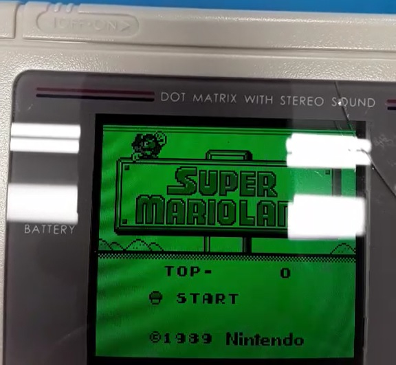
For myself, I believe I am going to call this project finished now. The minor thing with the small gap above the Wii port isn’t a huge thing even to ocd me. The 3.5jack hole was an issue I wanted to resolve though. I was going to also close the SD Card slot. I decided not to as the 3d mounting plate behind it does reasonably prevent someone sticking something in there and it is a bit of ventilation. I have played several games of Tetris on it and last night I got to the final Boss in Super Mario Land. It seems to work well, it is fun, provided the game itself doesn’t get frustrating. Thanks for reading and have fun.
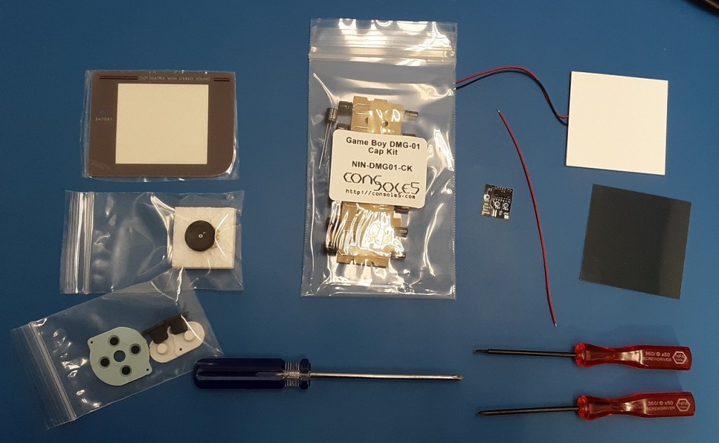
The only Vintage Game system or computer I have kept is my Game Boy DMG model. Based on the serial number I am guessing it was built in mid 1990. I had it from new and put a lot of hours on it playing games. It has seen better days. It was kept inside a case and never it an attic where it got hot. The case is pretty close to the original color, maybe some light yellowing. The display was missing lines, the glue failed on the screen cover and it fell off. I tried to glue the screen cover back on with super glue at some point, that held it on but ruined the “paint” on the under side of it.
The audio was being flakey on it at times. The screen even when it had the lines was well a DMG Screen.. I picked up some parts from Console 5 and somewhere else possibly on Ebay for my first pass of working on it.
So just as I said this was the “first pass” of parts that I purchased. Many of the items ended up not being in the Game Boy when I was finally finished. I broke the new Glass Screen cover, I did not use the replacement Volume pot, I did install most of the Cap Kit. The Button pads, were the wrong ones for the DMG. There also a back light kit with the Bivert board that I installed initially. Finally some Triwing drivers. It turns out my early Game Boy doesn’t have any Triwing Screws in it. It is all Philips screws. It isn’t in the picture, but as I had concerns about audio I did get a speaker as well, which I did not use.
It wasn’t too bad to clean up the old screen, you can see where the glue I had stuck it back on with years ago pulled the paint off the back of the plastic screen. I did have an issue with the new Glass Screen though.
Backlight and Bivert Mod:
So the first pass I went with the Backlight mod and the bivert board. The board was great. The removal of the old reflective layer was bad. Looking at the before picture, my screen wasn’t the best to start with.
Installing the board went very well following the provided instructions. There are 2 pins there to lift on the display connector on the CPU board side. The board is basically a carrier board for an inverter ic, the chip inverts the display. The light areas become dark and vice versa with it. With the Back Light rather than the reflective unlighted screen it makes it look better. The next part of the process was to take the reflective layer from the back of the LCD Screen. It was very tight, and while I got it off the lcd was missing more lines. I have seen people manage to repair the missing lines, but mine have been going bad since back when I was still using it in the 90s. Even so, it looked so much better with the backlight.
Original with my old clip on light.Back Light Mod with the bivert board
Yes it is missing more lines and even a couple horizontal lines now. Yes the Glass Screen broke installing it. The screen broke because it was very slightly oversized. I installed most of the capacitor kit, with the ones on the LCD, Power, and Audio boards. I tested the new ones and the old ones at the time on my component tester, none of them appeared to be bad. I left 5 of the 6 capacitors on the CPU board alone due to the other capacitors appearing to be fine, and due to being disappointed in the outcome of the screen, the glass cracking, and the fact that the audio issues didn’t clear up with the new capacitors.
Even in that condition the Game Boy was improved. I played it a bit like that. If the LCD wasn’t missing so many lines I would have kept it that way. It looked so much better and I wanted it keep it near original. That is why I didn’t go with one of the full LCD Replacements to start with.
On to a new LCD:
With the LCD not working properly though, I did end up getting one of the Replacement IPS LCD kits. The audio issue also ended up getting worse.
The instructions provided with the new LCD Kit worked out very well. This is an old project that I didn’t document much at the time. I did take a few before and after pictures. I would say the kits were fairly polished when I purchased mine, and they have been refined since.
The IPS Screen looks great, and has various color options to choose from. It doesn’t have the ghosting of the original lcd, which is a nice plus on fast moving games. The IPS Screen is the V2 or V3, which is now an older version of the screen, I am sure the V5s are nice these days. I put this in a few years ago now though.
Once the IPS Screen was installed the screen looked great minus the cracked glass cover. To fix that, I ordered another Glass cover, this one was also oversized, I filed it down with sandpaper on the edge to get it to fit. I also purchased a few more games for it to play with.
On to Sound Issues:
I was still having issues with the audio and it was getting worse. It would often not be working at power on, and then it may start working after a little while. With the audio getting worse I packed it up and let it sit in the case.
With Joes Super/Game Boy Console project catching my interest, I wanted to see if I could finally get my DMG back to full proper working order. Initially I thought maybe it was the audio jack. The Audio Jack has a switch built into it, when there are headphones plugged into the jack the internal speaker is disabled. I also wanted to look at the capacitors that were replaced and the ones that weren’t replaced. Looking at the Schematics for the CPU Board, the electrolytic caps are mostly audio related. Because I was working on the Super Game Boy Console, I let the DMG sitting in the case mostly. I wanted to add the Multiplayer Game Link function to the Super Game Boy Console, so I didn’t want to risk breaking the DMG before I could get that tested. I finished up the Super Game Boy Console recently (check my post about it if you are interested).
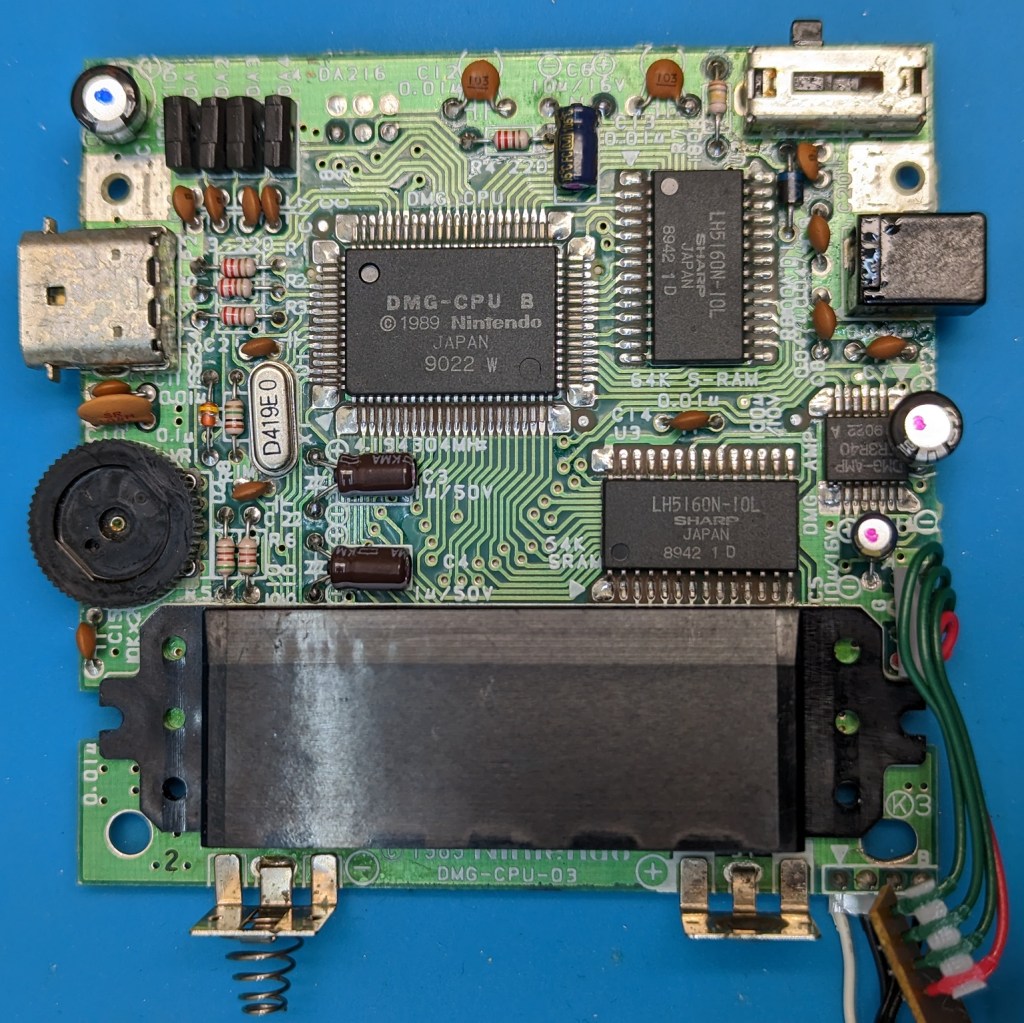
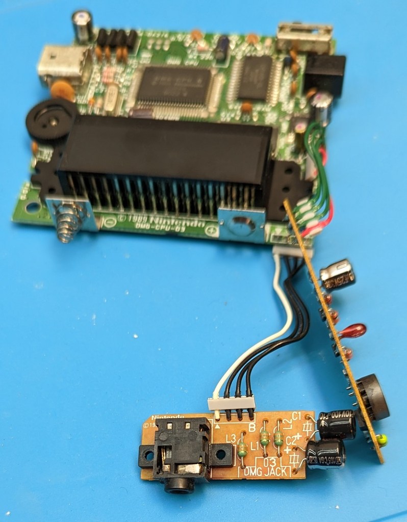
Last week after getting the SGB Console done and the Multiplayer tested I took a look at the DMG again. The audio is completely dead out of the speaker. I plugged in head phones and only had one channel of the audio and a lot of buzzing. I then took it apart, looking it over I didn’t see anything obviously wrong. The capacitors that were changed looked fine. I was able to tell that the CPU Board had 5 original capacitors still on it, as only one was replaced on it. The Audio Jack which was still a question for me has a lot of oxidation on all the exposed metal on it. I have seen other connectors do this at times. This socket has a switch in it that disables the audio. I had previously tried to clean it with contact cleaner but nothing changed.
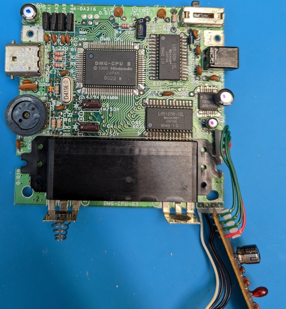
Today I went to look at it further. I replaced the 5 remaining capacitors on the cpu board. I did test the capacitors I removed and the new ones before installation. With the tester I have for them, the old ones appeared to be fine. I did put quite a few hours on the Game Boy back in the 90s, but likely no where near used them for their rated hours at the temperatures the Game Boy runs at. I probably wouldn’t go to the trouble to replace the Capacitors on a DMG again anytime soon. Certain hardware from the later 90s has bad capacitors in them due to defective design or bad mix in the electrolyte etc. I also feel capacitors from the early 80s especially in equipment that gets quite warm, will have a greater chance of being in need of replacement. In some of my retro computers and other devices I have found capacitors that even my limited tester indicates are out of specification.
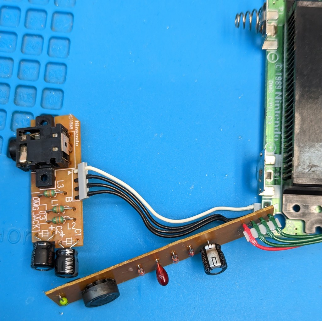
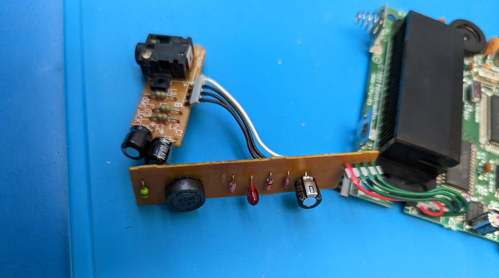
I looked over the boards again, but didn’t find any visible problems. I did clean up and redo some solder points, redid the power switch, the Link Port and some other solder points incase they had been stressed although I had not seen any visible cracked solder around any of the pins. I cleaned the tarnish off the exposed metal parts of the audio jack. I then removed the audio jack from the pcb with my desoldering gun. It shouldn’t have been awful to get off with the solder sucker. I tested it, and none of the pins were connected once it was pulled out. Checking the schematic, and tracing the wires I found that pin 6 of the audio amp is to be switched to ground, and that is the pin of the audio jack that goes to the white wire on the audio board. Testing again on the jack there was no continuity to the other half of the built in switch. I plugged in a 3.5 plug and it didn’t connect the switch. I was just able to see where the switch moved when the jack was inserted. I sprayed it with contact cleaner and used an Xacto blade to get a little under the switch. I was able to get the contact working again spraying it again and using the 3.5 plug in and out a number of times. I tested and had under 2 Ohms then. I also tested the 3 connections on the 3.5 plug and all are making good contact now. I then soldered the jack back onto the pcb and retested the switch and 3.5 plug contacts again.
Orange = Pin 6, Red to GroundSwitch Contacts in here..
I have some other pictures of the boards before cleaning off the flux and reinstalling them. While I had them out, I put contact cleaner in the Multiplayer Link Port, the Volume pot, Power Jack and Power Switch.
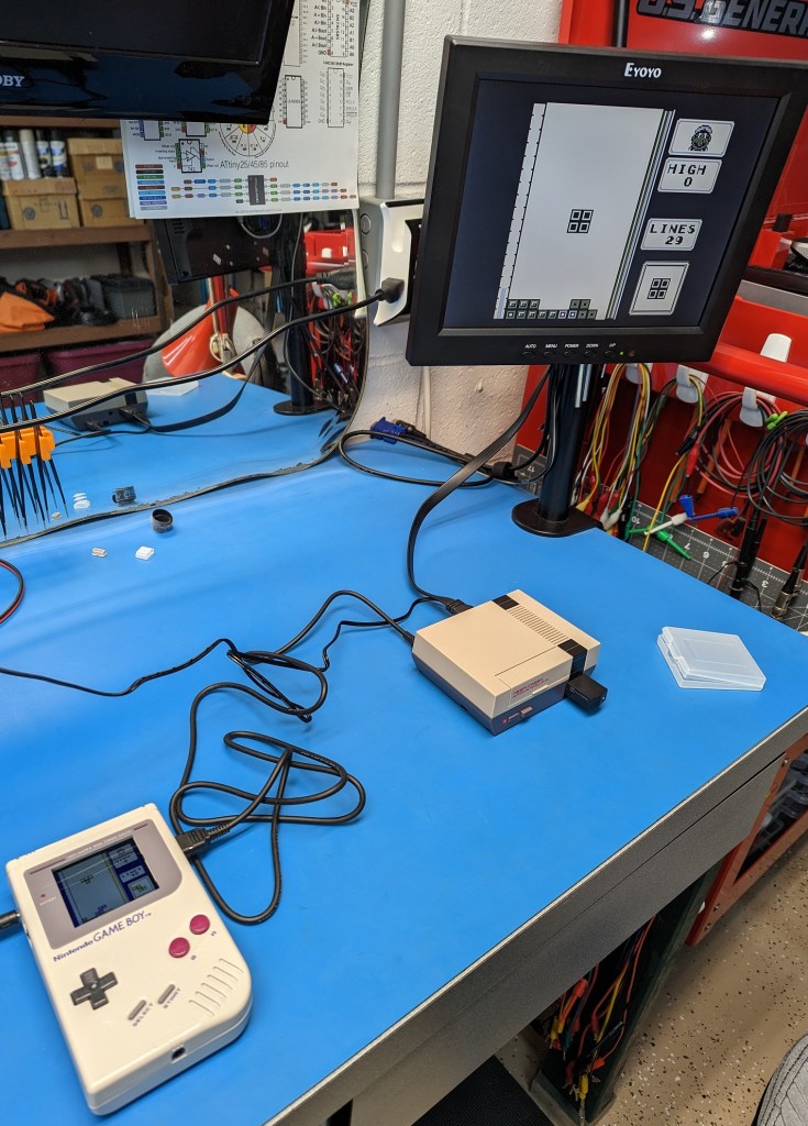
The internal speaker worked properly again after reassembling the DMG. There is a bit of hum, but that is mostly from the AC Adapter, when on batteries there is nearly no hum. I don’t remember the hum being there in the 90s when using the same AC Adapter. In looking into the hum, it was reported that the IPS LCD kit adds some Hum to the audio, due to higher current draw, well that is what they said. Maybe it also is making some of it due to interference from it’s operation being picked up in the audio amp or something. It is not very bad, but certainly is more present when on the AC Adapter. It was worse actually before cleaning the power port, power switch and other contacts, I thought it was from the Audio Amp itself, but it was that same hum just worse before working on it this last time.
Reassembled and Testing:
The Directional Pad didn’t work properly though. While I had it apart, I had switched out the contact silicone pads, the Start, Select, A and B buttons all worked properly with the new pads. I took the DMG apart again and checked the pads. I cleaned the contacts on the PCB. I then tested conductivity of the new Directional Pad and also the Original Pad. The Original Pad was more conductive. I cleaned it lightly with IPA and reinstalled it. I also looked at them, and the new pad is designed just a bit differently. I tested the DMG again and the directional pad was working properly. I had swapped them as they are old and they look worn. It also seemed the directional pad wasn’t always working as well as I liked. It seems fine for after cleaning, hopefully it holds up.
The volume control is good and smooth, it isn’t scratchy at all. The power switch works properly making good contact, and the power jack is giving good connection too. The power cord could give some crackling before as it swiveled in the port on occasion before. It seems everything is finally working properly again. I’ll get a chance to play the old DMG again.
Looking at the photos from when I started working on the DMG, it has been over three years since I put in the Back Light mod and started putting the capacitors into it. It is nice having it finally sorted out and in good working condition again.
Trying a little Multiplayer Gaming:
Now I can pair it up with my Super Game Boy Console and play some two player Game Boy games.
I was watching the Andy West’s video of Joe Ostrander’s Game Boy Console project on the Element 14 Youtube channel. It was inspired by and earlier project video that Andy West had done awhile ago. In the new video Andy builds one of Joe’s v3.0 boards, and gives some details I will likely be missing here.
The latest version from Joe was v3.1 it uses a Raspberry Pi Pico, a Super Game Boy Cartridge with a few other parts to build a Super Game Boy Console in a tiny Retroflag NESPi case. With v3.1 Joe used the Super Game Boy Cartridge Port instead of the SMD Cartridge Port Andy had for the v3.0.
Here is the Video:
I liked this project because it included some things I could practice with and some new things.
Andy’s original project included the DMG Link Port for Multiplayer games, but Joes project did not. I looked over the schematics for the SGB and the DMG as well as Joe’s version and it seemed simple to add that feature.
The Super Game Boy can play the original Game Boy DMG games. The Super Game Boy didn’t have the Game Link Port, but the CPU was the same except it doesn’t have the Nintendo name scrolling down the screen at power on (unless the cartridge isn’t recognized properly you never see that screen at all).
I was able to contact Joe and he sent me a copy of the Easy EDA Project files. He had it listed at v3.1 at the time with the Super Game Boy Cartridge port. I modified Joe’s main pcb to add in the parts required for the Link port. This was the first time I have worked with Easy EDA. It took me a little bit to get used to working with it. I have used Eagle in the past for other projects, but for Hobby work it is very limited in board size. Easy EDA can send an order to JLCPCB for production, or your can have it generate Gerber files to send to your favorite PCB Producer. I made a Footprint for the DMG Link Port is a recreation of Gekkio’s KiCad DMG Link Port KiCad footprint in Easy EDA, so that I could make the DMG Link Port adapter board.
There is a single Pi Pico that handles controller input and generates the VGA Video output. It also uses a VGA to HDMI Adapter to take the VGA output from the Pico to HDMI including the Audio.
It has options to either use a NES Controller port and Controller, or to take a Wii jack and use a compatible controller for that, be it one of the Wii Classic type controllers or one intended for the NES Mini such as I have used. There is different firmware for the Pico depending on which controller type you go with. Joe has both versions ready to go for you in the .u2f format. I went with the Wii port, and the cheapest way for me to get it quickly was to buy a Wii controller extension cable and salvage it out of there. I figured it was likely I could salvage and reuse it, and while 3 of the pins were cut short, it did turn out to be the regular through hole port and works just fine in my case. There are different Controller Port Mounts and as I said Firmware depending on which controller option you go with. The firmware is in the .uf2 format that is very easy to install to the Pico. You first download the .uf2 that you need on your computer, then get a usb cable for the Pico, hold the button on the Pico as you plug it into the USB port on your computer. You can release the button then, if you did it right, the Pico will show up as a drive on your computer. From there copy and paste the proper .uf2 file into that drive. The Pico will upload the code and reboot itself automatically. The files are gb_vga__pcbv3_nes_controller.uf2 for the NES Controller Port and gb_vga__pcbv3__nes_classic_or_wii.uf2 for the Wii Controller port (filenames prior to 1/15/23).
Update: 1/15/23 It appears Joe released an update for the code on the Pico, the new version only supports the Wii type controller. The Home button now brings up the OSD Controls. I’ll have to check it out later.
The Controller Ports also require different Adapter PCBs and wiring as well depending which you go with. The PCBs are labeled on both the Main PCB and the Breakout Boards. The pictures of my prototype board are not the final design for v3.21 on the final one (which I show a render picture of at the end of this post) you will find the “<– NES” and the “<– Wii” markings on the silk screen. Be sure to use 3V3 for the Wii Breakout. I have updated Joe’s Wii Breakout board to list 3V3 instead of VCC. For the NES use 5V and Gnd just as the board is labeled to accept.
Wii Controller Breakout BoardOriginal NES Break Out Board
There are numerous parts. Much of it is surface mount, minus the Pico and the reused SGB Cartridge port.
Wii Controller Breakout Board PCB (Optional this or the NES Breakout)
wii_jack_w_holes_v3_21
NES Controller Breakout Board PCB (Optional)
nes_breakout_v3
DMG Game Link Multiplayer Breakout PCB (Optional)
dmg_link_v3_21
USB Power with Data PCB (Optional, to Program the Pico in the case)
pcb_v3_usb_w_data
BOM
I used the USB Port from Retroflag instead of the optional “USB Power with Data PCB”, I don’t expect to need to reprogram the Pico that often. I ordered in Joe’s Wii controller PCB. I also ordered his Power and Reset button board. I ordered the version of the Main PCB that I had added in the Link Port parts. For the Link port I ordered in a DMG-07 Four Player adapter to salvage off one of the Link Ports as Joe suggested.
I have since created a somewhat more refined version of the Main PCB and some other PCB changes. Keep in mind the BOM list above is for the v3.21 board not the prototype I have pictures of here. Some component designations have changed and D1 is now a Diode Array on the “finished” board. I also created the DMG Link breakout board. I used the protoboard version as seen in the pictures, but the Mount for the DMG Link board is designed for the PCB.
The first part was to do the main PCB modifications. I ordered the required boards, I also found out you can have them panelize the boards for you. I now have a crazy number of Wii Controller Breakout boards for the same price I would have paid for 5. That opens up some real possibilities for when I have a small board I would like more of.
The next part of the project was sourcing all of the other parts. Joe’s BOM at the time had a mistake on it the 22pf capacitor listed was a 0201 imperial part. The BOM above is listing a 0603 imperial sized part. That is an easy mistake to make as 0201 imperial is 0603 metric.. The parts listed above are the specific part numbers I ordered except for the wire. If you don’t care to do the Link Port, then you don’t need R15-R18, D1-D5, or C5-C8, or the DMG Link PCB, and the Link Port itself.
Once I had all the required parts it was time to prep the various parts. For the Retroflag case, I had to desolder the USB power board from the Power Reset button board so I could reuse it. I then had to desolder the Power and Reset Buttons as well as the LED and the LED Light pipe so I could reuse them. I then installed the Power and Reset Buttons and attached the USB power board to the new PCB. Just a note I missed seeing the pad for the Resistor for the LED on the board, I revised the board so that was listed on the silk screen and installed a 510 Ohm resistor on it ( I expect a 1k resistor would do well too, if you don’t want it so bright).
The case requires a bit of modification to fit the new parts. The opening where the two USB ports needs enlarged depending on which Controller port type you go with. The top needs modified by cutting out the opening for the Cartridge to get in. That requires taking the front center post out of the top as well. Be careful to not remove too much. I did have to slightly trim some of the top posts (but not all) about the thickness of the PCB to get it to fit nicely. The back center post was removed on mine as well using the PCB as it was on the prototype. I revised the PCB so that v3.21 should let that back center post remain now. To see how much the top posts needed shaved down (about the thickness of the PCB) just check the fit of the PCB laying in the top of the case, it basically needs to sit level and about flush with it. For the Pi Pico to clear the top, I had to remove the tabs and a little bit more where the fan is to snap in. I think if the Pico is mounted with short posts it would have more clearance. I decided to mount it with some header sockets so I can remove it if I want/need to in the future. For the bottom there there is some material that needs removed from under where the green mounting part goes in for the Controller port. That part is where the Controller Port is mounted as well as the hole in it is the one hole that holds the VGA to HDMI board in place. Below you can see the modifications to the case. I didn’t think to take “before pictures”. You can also see the new Power Reset board, USB Power board as well as the Wii board mounted into the bottom of the case. The Link Port will be added to the lower right cavity later.
Beyond the case prep, and pulling those parts from the original Power Reset board there is the Super Game Boy Cartridge parts to deal with.
With the Super Game Boy, we pull the board. We need to salvage four parts. The CPU, the two Ram Chips (they are identical) and the Cartridge Port. Below you can see the board after those parts are removed. I did clean the flux from the board and kept it if I find a future use for it. To remove the chips I used the technique that Andy West showed with Low Temp Solder alloy. I watched him do it a couple times, I then watched some other people using it to remove chips. For me I wasn’t having all that great a luck with the CPU, so to make the process go easier I used my hot air station to make it easier that helped me a lot. It seemed that in Andy’s video it must have also taken him awhile to get the CPU off, I felt better using the hot air as the heat was applied for less time than it was taking with the iron alone. I am sure I would have gotten it with just the iron, but it is also nice to use the hot air station for more than heat shrink now and then. That low temp alloy is weird stuff, the flux smells odd too. It is the first I used it. Be sure to clean the low temp solder from the chips with some solder wick after removing them. It needs removed as it is not good to have it on the final board it doesn’t work as well as solder.
For the Cartridge Port, I used some money from Christmas to purchase one of the cheaper desoldering guns. I also used the new desoldering gun to remove the switches from the Power Reset board and VGA and Audio sockets from the VGA to HDMI adapter. I could have done it with my desoldering iron, it is shown in one of my C64 refurbishing posts. I also used it to pull the Link Port from the DMG-07 4 Player adapter.
Super Game Boy after removing the required ICs and Socket to be reused.
Below is the VGA to HDMI Adapter after it was prepped for installation. The VGA Port and the 3.5mm Audio port had to be removed. Even with the desoldering gun, I ended up pulling some of the through holes out of the VGA port, nothing that was a problem though in this case. It has 5V (Large Red), Ground (Large Green) for power that go over to the Power Reset board. Then the Dark Blue (Left Channel) and Brown (Right Channel) wires go to the pad for Left and Right audio over on the Main PCB, Ground is all joined so that doesn’t need a wire in this case. Then we have the Red, Green and Blue for the R, G, B pins then the Orange ( V Sync) and Yellow ( H Sync) and I did wire the Black wire for Ground there. The small wires are 30awg Wrapping Wire.
Below is the main work done on the unit. This was before adding in the Link Port.
Above you should be able to make out most if, not all the wiring there. I did put 2.5m screws into the Link Port holes to give it stability. You can possibly make out the green 3d printed washers under the screw heads. I didn’t want to scratch the pcb, and there is one trace right there by the left screw. The revised board has that trace relocated now away from the hole.
There is not too much going on on the top side of the PCB. The picture above was before I added the screws to secure the cartridge port. It is just the port and the Pico. I am using header sockets and pins so the Pico is removable if needed, but that shouldn’t be a big deal to solder it in with the normal pin headers. If you go to put it on header sockets, you may want to test fit it in the case to make sure it will fit. For me it got pretty close to having to cut out all that area where the fan is intended to be mounted.
To add the link port I modeled a part to sit down in the remaining cavity in the bottom corner of the case. I put the 3d printed link port mounting plate in for a test fit and I could not get it back out. Luckily my chip puller was able to get in under it and pop it out without damaging the case. The part is made so that you put the Game Link port in place and then press the 3d printed part in place, it clamps the port in by the little ears sticking back on it a bit. The main thing is to get the opening made in the right place at the right size for the port. I made a template of the port shape, then drilled a hole where it would be inside the area to help me get an idea on placement and got lucky enough I had it right in the end. I used a combination of small drill bits and an Xacto Knife.
I used two of the remaining shorter smaller diameter black screws from Retroflag to screw down the port PCB (or protoboard in my case). I didn’t expect the green printed part to fit in so securely, if it works loose I can just add a dab of glue and it shouldn’t be able to move. I do have all 4 sides fairly snug and the Link Port is put out into the case plastic so it can’t lift out on that side. I used Design Spark Mechanical to make that adapter mount, it was quite easy, far easier than getting something that dimension specific done in Tinker Cad. I have to spend more time using it. I probably could have made the Ampi case in it far more easily if I had stuck with it.
The image above is a view of the DMG Link Port Mount model. The first test print worked perfectly, which is uncommon. It was a snug press fit, the port fit right into the cavity for it, the screw posts printed solidly and the holes in it are the right size for the screws. You have to put the Link PCB with the jack on it while the mount plate it loose yet, just work them in together and you should have a good fit for both. It may look like the screw posts are back a bit far, but that is because my piece of proto board is a little shorter than the PCB I designed. I made the mount to match the PCB design, not the piece of proto board I am using.
Above is are renders of the DMG Link Port Breakout Board.
The unit is complete now and tested. I used it awhile without the Link Port as I was still sorting out some things on how I wanted to install it. I also had tested the Link function and it wasn’t working due to me not knowing that there is a twist in the cable, so two of the pins had needed switched with how I was connecting it up.
I have the revised v3.21 board shown above as it is now. Like I mentioned some component designations have been changed. D2 R18 etc. I have relocated some pads. I put the Wii pads together by bringing down the 3V3. The Work Ram is lower on the new revision. I think it may now clear the center front post in the lower case body, but with it where it is on my prototype it just gets in the way a little bit. I have added a notch in the board that should allow keeping the back center hole in the case instead of cutting the post off.
Joe has pulled my Fork into his project and corrected the Left/Right Audio being flipped as of 1/20/23.