I recently came across the IECBuddy addon for the RAD REU unit when I noticed it had a firmware update released. This IECBuddy is a device that connects to the RAD REU via USB and the Commodore 64/128 via the IEC Serial port. It can read and use D64, G64, D71 and D81 disk images. It can also operate as a virtual printer. For the disk emulation it can operate several of the popular fast loaders.
The IECBuddy uses a RP2040 or RP2350 microcontroller. Which are the typical RP Pico and RP Pico2, as well as other styles of the boards. The boards have a minimum of 2mb of onboard flash, some as much as 16mb. The IECBuddy uses 1mb for the program, and the remaining flash memory can be used to store disk images. 1mb is enough for about 6 D64 disk images. The Buddy will operate without the RAD, but the RAD is what you use to copy the disk images to the Buddy’s Flash memory. The REU can transfer files from it’s SD card into the Buddy via a new menu.
The Buddy can be build various ways. You can make it up on a bread board with a RP Pico or another board. You can order one of various PCBs for a RP2040-One board. There are firmwares for the “Barebones/Micro” types as well as the “Mini” and the “Max”. The Barebones is such as using a breadboard or just wiring a board up with some cables/connectors, the Mini is the PCB Version with a RP2040-One. The draw back to those is the RP2xxx works at 3.3V but the Commodore 64/128 work at 5V levels which may damage the RP2xxx. The next level is the Mini, it also has a PCB design for the RP2040-One footprint board, but includes level shifters to make a safe connection between the 3.3V board and the 5V based Commodore 64/128. The Mini also has the optional OLED Display. The Max board is everything from the Mini plus it adds support for Parallel data transfers with some additional cables and connectors.
I ended up buying some RP2040-Zero boards. They are similar to the “-One” board, but the -One board has a USB A male port built into the PCB. The “-Zero” board has the same pin layout but instead has a USB C female port. I had a little different idea for what I was doing with this project than the existing options.
I first built up the Barebones board per the IECBuddy github. I also added the optional eject button, which what it actually does is switch from one disk image to the next. To test this, I had to take my RAD REU that I built with a pi3 A+ out of it’s 3d printed case to get access to the USB Port.
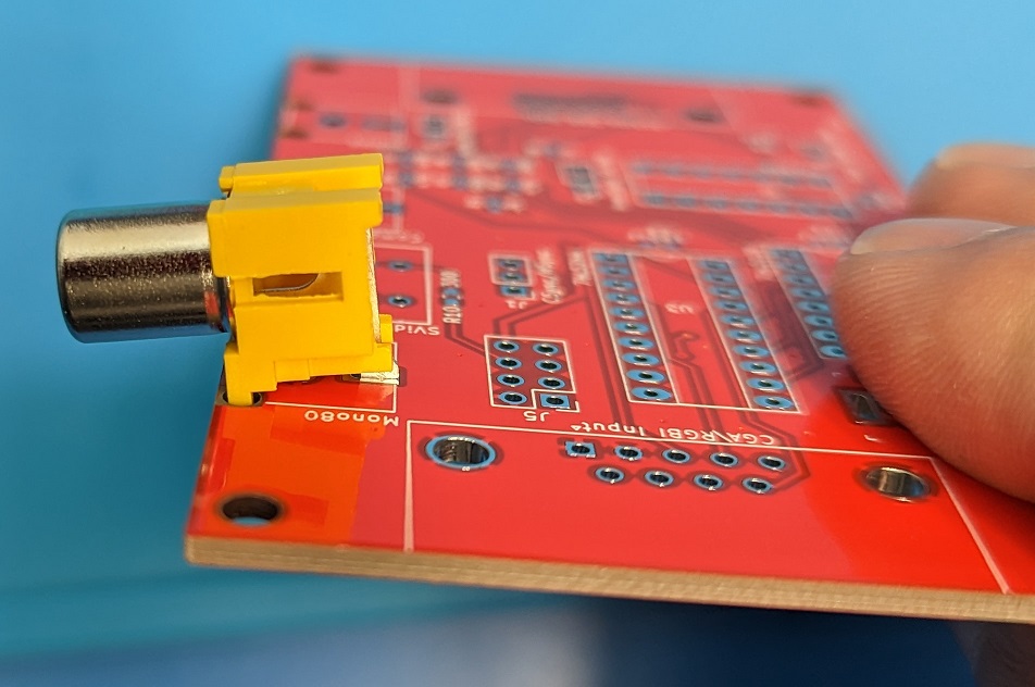
The first image is showing that when soldering up the IEC connector, that I used a jack to help keep the pins in line. The black plastic of the DIN connector can easily melt and deform when soldering. Having it plugged into a port gives additional support when heating. What I don’t show here, is that after testing that the Buddy worked, I then used Liquid Electrical Tape to insulate all the pins and wires inside the shield. This is at this point a very Barebones build. To program it I used the precompiled .uf2 file posted on Github.


Next I tested it with the RAD REU on one of my C64s. To test initially, I had to take the bottom of the 3d printed case off of the RAD. The RAD needed the latest firmware, which when the IECBuddy is detected enables the new menu features. To transfer files to the Buddy, press “S” when you have a disk image selected, you can select multiple files for transfer at once. Then press “I” to get into the Buddy menu, and Transfer the files to the Buddy’s Flash Memory.
The one thing to note, the RAD Github mentions “S” to select the file, you see the little icon in the one picture of the D64 that is selected. Though the RAD help menu doesn’t list the “S” key. The other oddity is inconsistent use of navigation keys. To exit the Buddy menu, you press “<–” up in the top right of the keyboard, but then to exit the RAD main menu you use X.


With finding that the Barebones Buddy build worked, I went on to modify the RAD REU 3A+ case. First I just used the Dremel to cut it out an opening for the USB Port. After that, I went into Tinkercad and modified the 3d Model. I then reprinted it in the same material as the rest of the case to match. That turned out pretty good. That modification “may” let you use the RP2040-One boards on Github, but it may not provide enough clearance to insert the -One board into the usb port. I am not buying any -One boards to try, but I will be posting the modified case up on Printables and Thingiverse as a remix.


After that I went on to make the revised Buddy. I have a second RAD REU built, I was using it with a pi Zero2 instead of the 3A+. There is an alternate RAD REU PCB design for the Zero2, but I had ordered 5 of the gold finish larger boards. This makes for issues with the cases, the USB Power Port is not accessible if I use the 3A+ style case, the SD Card is also not accessible. There is also a bit of free space in the case. With my RAD REU with the 3A+ in it, I do power it externally like is recommended, though for this project I am powering it by the C64 cartridge port. I don’t use “original” power supplies, and the supplies I do use are capable of providing more power than the factory units. Over time and using it, I guess I will find out if it is stable. If I find it isn’t, I’ll have to work out adding a way to connect up the USB Power.
That meant, I came up with the plan to stick a modified Buddy inside the case. I kept the “barebones” build without the level shifter ics. I wanted the LCD screen though, so I had to compile the firmware myself. This was not fully documented as to what “Boards” to add to the Arduino IDE to use.
To compile the firmware, I used Arduino 2.3.8. I added “Raspberry Pi Pico/RP2040/RP2350 by Earle F. Philhower, III” in the Board Manager.
I set the board type to “ArtronShop RP2 Nano” since my RP2040-Zero “identified” as one, though it certainly is a different layout. The Flash is set to Sketch 1MB, FS 1MB, always set the board to Sketch 1MB with the FS being the remaining that is the storage for the Disk Images.
To enable the LCD Screen, on Pins.h uncomment the lines for the screen. Below you can see those as line 49 to 52.
Then I just programmed it like any other board with Arduino 2.x. That process does look to create a temporary .uf2 in the compile output, but I don’t know how to just make a uf2 that can be used directly.


Once I uploaded the new firmware, I wired up the LCD to test it was working. I also had started working on a modified 3d case. With the bottom part, I closed the original SD Card slot, and made an opening to access the Zero2 SD Card, it can at least be accessed with small pliers or tweezers. On the back I changed the original USB Power port to hold a 6x6x4.33mm Tactile button and have a 3d printed button insert. On the other side I opened the round hole up to accept a 3d printed grommet to put the IEC Cable through. For the button insert, I had to shave off a bit of the rim due to the 3d print sagging on the top edge. After I had that issue, I modified the case bottom to have a more teardrop shape tip at the top, that should minimize that issue by giving more clearance.


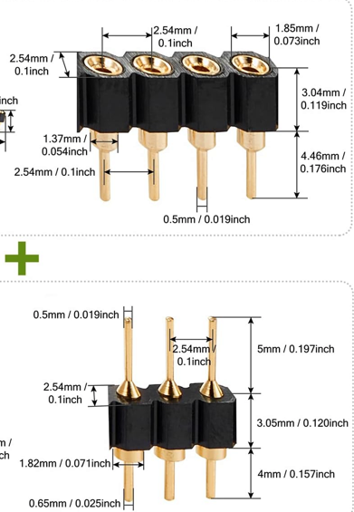
The LCD is wired up with what are often called “turnpins” or “roundpins” or “machinepins”. On the RP2040 board, I installed the sockets. For the wires on the LCD, I cut the top pins off, and soldered on 30awg wrapping wire. Then used liquid electrical tape to give strain relief and insulation to the wires. This makes up fairly compact removable connection.


With the revised case back and lcd screen working, I next worked on a customized front for the case that the LCD can be fitted into.
The other item I had to make up was a very compact USB C to Micro USB cable. I did not have any USB C “data” connectors, so I took a basic USB C cable that is only the 4 wire usb internally and cut it down adding a Micro USB connector to the end. While again using Liquid Electrical Tape to seal up the Micro USB connector. To give it room to fit, I did leave the shell off the Micro USB connector.


Here is the case with the LCD being fitted with M2 screws that are about 3mm long.


You may notice the LCD doesn’t look right when it was powered on. This was because I had the spacing incorrect for it, and flexed it when screwing it in. That ended up ruining the screen, I had pulled it apart and it was working a little better, but I put it back together and left it in the case not fitting well overnight which seems to have ruined it.
I have since revised the case to not put pressure on the lcd, but the damage was done. For now, the top edge is working properly showing the file selected, and part of the rest is ok, but it is quite messed up. I have a second screen, and will swap it out once I reprint the case. As you can see there are some defects in the print. This was the first revision, and I had reprinted the one with the fixed LCD mount. That second print looks better than the one pictured here, but still has defects in it. I am not sure what filament I want to reprint this in. When I take it apart to swap the LCD, it is almost certain to break one of the top clips. It has broken on any of these cases I have ever pulled apart.
The screws I found to work with this case are #2-56 x3/4″ long. Nearly everything I use are metric screws, there is possibly a metric size that will work too. After testing, I did print out a resized RAD REU Label, that can be seen at the top of the post. The label color is not perfect as it has a magenta hue in the text, but this also isn’t intended to be the final case so I will sort that when I change the case out. The label is a perfect fit though.
Below is an internal view of the modified case bottom. On the left you can see the 3d Printed TPU Grommet for the IEC cable. The right side has the 6mmx6mmx4.33mm tactile button. The tiny button cap is inserted before the tactile button. The button just fits, but it is loose, so once I had everything ready to close up, I put a small dab of hot glue to keep it from sliding out.

Now for the limitations on this device. It is not a cycle exact emulator which is what the pi5141 attempts to be. I guess it is more like a SD2IEC, but it isn’t the same thing as that either. It has built in support for JiffyDos by default, as well as the Epyx Fastload, but with the RAD REU, you can’t have the Epyx Cartridge installed. If you made modified firmware you can enable Final Cartridge 3 and some other cartridge based fast loaders, which again can’t be connected to the C64 the same time as the RAD REU. Maybe there is a way, like with the multicartridge backplanes.
That leaves it with JiffyDos, and for the Max variant maybe DolphinDos or another parallel transfer mode?
The C64 I have been testing this with is the one I have setup with JiffyDos and JaffyDos (modified JiffyDos). I did test it with that, and it worked pretty well with it.
The other limitation with the Buddy is if a game uses some special fast load method that it may not load with the Buddy. I was surprised to find Aviator 2 which is a modern game had this issue. The game loads the initial screen just fine, but then that second load starts the Buddy fails out with an error, I guess the first part of the loading loads in it’s own fastloader. I don’t know how many games or other programs are like that.


I did try disabling JiffyDos, but it still fails to load. I guess when you find these incompatible loaders on games, there just isn’t a way (at this time anyways) to load them?
I am overall happy with this project. The documentation is good at the Github site, between there and the REU site. The only oddities being the missing “S” command in the RAD internal Help screen, unless somehow I missed it. Then how to compile not indicating exactly how or what name of the “Board” to load in the Board Manager.
https://github.com/dhansel/IECBuddy/
I was tempted to make a PCB design for the build, but there isn’t much to it. I would have tried to fit the level shifting ICs if I had a pcb though. They would have been a mess to try to fit in without a PCB. The way it is now, the RP2040 board just has a bit of Kapton tape on the bottom.
The case has been a small disappointment with how poorly the top piece printed, I had hoped it would print out nice with this filament. I don’t usually have print quality problems with the case, it is not a fault of the design, this filament is just abit problematic. I’ll see what I want to do for the filament and print a new case for it, at that point I will swap out the damaged LCD. When the LCD is swapped, and I am sure it is safe with the revised case design, I will look at posting up the remixes at Printables and Thingiverse.
I really didn’t need one of these units, as I have the pi1541. That is why I wanted to make this compact version. I figured this can be useful in how small it is, and how easy it is to hook up. I didn’t want to use another 3A+ in my second REU, and wanted to make a case usable with the Zero2 and the larger REU Pcb combination as well. This took care of two things at once. It also seems to be about the perfect combination for exploring GEOS, using the RAD and putting the disk images on the Buddy.
The Buddy can be used in combination with the SKTool program and a pc to load files into the Buddy’s Flash. This would be a bit limiting with a 2mb board with it only being able to use 1mb of that for storing 6 disk images. This may be practical with one of the 16mb boards which would hold up to 15mb of disk images. Though at that point, maybe the SD2IEC would be a better choice? I really don’t know how the two compare as I have never used one.