Part 1: Prototype Post
Part 2: PCB Design, Schematics and BOM
Part 3: Boards Assembly and Testing
The KiCad files, Gerbers, Schematics, Bill of Materials and 3d Models are all released at Github:
https://github.com/Markeno76/rgbi2rgba
I worked up some 3D Printable Cases for the C128 RBGI/CGA to Analog RGB Adapter boards.
I am trying to get away from TinkerCAD, the AMpI4 case (See the post on that here) that I made in TinkerCAD turned out for me. It was a lot of work and it is complex to make modifications to that model when I need/want to.
This time I went back to DesignSpark Mechanical, which is what I started with for the AMpI4 case. I wasn’t ready for a project like that as my first real attempt to make anything in it. This time it was painful as well, but it is a much easier project. I learned a fair bit, but have a long way to go. The case hasn’t turned out perfect, but I’m quite happy with it overall. I make make a couple adjustments to it yet. To start with a made up a mockup of the physical board. That took awhile, then I realized I could export a 3d model of the board from KiCad. When I found that option, I went back and partially started over. I then just had to model the various ports. I did not size them to real world size, I upsized them to be used as the penetrations in the case exterior.


I ended up with making two prototype case prints. The first one showed me the primary mistakes. The SVideo Mini DIN Port opening was too small. The port was accessible with it being properly uncovered, but the outer plastic of the SVideo cable couldn’t get into the opening as it has to go down flush to the port. The RCA ports were correct, they don’t go the whole way down around the outside. The 5V Barrel jack was properly sized for 3 different power cables I tested with it. The DE9 was right. The screw holes placement for the HD15 port were 1mm to high, the whole port was 1mm to high, the cutout and all. This may be due to me using the DE9 measurements as the basis for both openings. I resized the Mini DIN opening, dropped the screw holes for the HD15 port and made the case thicker overall. The first case closed properly, all port alignments were right (short of the HD15 height), the mounting holes for the board and the posts were all correct. I made those adjustments and printed another test of what is now the “all” version of the case. The revised case printed out well, the Mini DIN Port cable now fit properly, the screws for the HD15 were aligned properly and the case was not as flimsy feeling. Once that all checked out, I went back into DesignSpark Mechanical and made up my variant cases from the initial “all” openings case. It was easy to make those variants as it only took a couple minutes. If I was familiar with it I bet it would be more like 2 minutes to do the modifications. I am still very unfamiliar with it, but I like the greater control with the model compared to TinkerCAD.
There are 3 versions of the case, the “all”, the “CGA” and the “C128” variants.
The “all” case has openings for all of the ports.

As you can see the case design is a split top case. There are no overhangs (except the DB/DE screw holes and the underside holes) that require support when printing. There is a slight rounding on the corners. With the settings I am using on my printer it takes about around 1.5hours per half of the case. I normally print faster on my Ender 3 Pro, but the filament I am using didn’t like that. It is some old PLA+ and that particular filament always gets moisture in it. To speed up the process I ended up printing each half on one of my two printers. That is why the filament is different for each, as I didn’t have two spools of the same color. I printing in PLA/PLA+ incase I wanted to paint the case. The color is an acceptable color for the use though. I plan on making up a version of the labels I put on my prototype to put on the tops of the cases. I’ll have to get ink cartridges in the printer before I an make the labels up though. The DE9/HD15 ports have the holes for the standoffs in the lower case shell. The bottom of the case has 4 holes in it for screws to go up through into the standoffs on the top half of the case to keep it shut. I don’t put the Standoffs in tight until I have the bottom screws in to prevent cracking something. With the case design, it does take opening the case to move the jumpers of course. I’d rather not have holes in the top for stuff to fall in, it is also hard swap jumpers in openings like that. It may be possible to rework the PCB to have some sort of DIP Switch. That makes another part to have to source, but it is possible to use that footprint for Jumpers too. DIP Swithes though are generally SPST, not SPDT which is what three of those jumpers need. I do have “mini” SPDT Switches, which I actually intended to install into the C128 type board, but I forgot to. They fit the 3pin Pin Header footprint, and have a narrow somewhat tall slide. These are used on some Commodore 64 (and I am sure other) New and Reproduction cartridges such as my C64 Diag/DeadTest Cartridge. I have also used them on some cartridges, like the C128 Multi Diag Cartridge I made awhile ago. For those mini switches it could be possible to design a case top that let you change them either with small openings, or even make extension caps that let you toggle the switches with the case closed. I don’t expect to be switching the configuration of the adapters often. The SCART to HDMI adapter was unstable in testing the games and was said to introduce lag, I’ll likely just use these with my GBS Control adapter instead. I’d love to be able to use them with my Sony PVM, but it takes a 4V Sync signal, I haven’t even looking at what may be done to adapt that from the ~1V Sync that normally is put out with RGBI/CGA.
The “C128” case is modified to accept my slightly custom RGBI board and has openings for the four Commodore 128 specific ports along the left side. It doesn’t have an opening for the DE9 Male port, as I am using a short “dongle” type cable out the side. It has a smaller opening where the 5V DC barrel jack would be and a second matched opening beside that for my two “dongle” cables grommets to rest in.

I use the short “dongle” cables there for the C128 version as I don’t want to have to make up short stubby cables to plug into ports. I also don’t want to make a custom Commodore AV Cable of some type. It gets more complex trying to find a port and jack for the Commodore AV Cable, then everyone who wants to make one needs to source the same “odd” port and jack. It is bad enough getting the Commodore AV Port “U” DIN connector. Since I am using that short AV dongle there is no good reason to make up a shot stubby DE9 Male to Female cable either. In my case that is part of an old DE9 Serial Modem cable. The grommets fit the cables snuggly and are from a case of grommets I picked up at Harbor Freight. I sized the holes to accept those grommets.

The third type of case is the “CGA” Case. It doesn’t have any of the Commodore 128 ports on the side, but has all the other normal openings in it. The case should be easy to modify with various 3d modeling packages, even with Tinkercad or such if you want different openings.

The case isn’t perfect but I’m happy with it. The holes in the bottom were meant to take recessed M3 screws. The recesses aren’t deep, or wide enough. I have already printed 4 cases today for just 2 adapters, so I don’t plan to rework the recesses. I also don’t have any tapered M3 screws of an appropriate length. It seems to close well with M3 screws, I made the holes in the top standoffs to be hollowed out quite deeply, but something like a 10mm or probably 8mm screw is sufficient. My cases are printed out of PLA on two different printers and the holes worked well on both, the holes are a good fit for the M3 screws on both, but each printer is a bit different. I thought of putting Threaded Brass Inserts in, which takes a larger hole, but there is alot of variation on what size and depth they need to be. It is hard to make a “universal” case when using brass inserts. I have some super cheap thin ones, them my good ones are massive.. When sitting the case together there is a slight pulling at the corners, but on putting the screws in the minor gaps close up tightly. With my cases the fact it is made of two different materials does make it stand out a bit, but I kind of like the look. It should print fine in PETG. I used PLA as I have more color options, and if I decide I want to color match it with paint, PLA is the better option. I like doing prints in Transparent PETG, but this is for use with an 80s Era Computer not an iMac. I have a couple opaque PETG filaments, but not one in a color that I felt was appropriate.


Above are pictures of the closed up cases from various angles. I also showed some bottom views where the screws are present. It is quite bland looking and you can’t tell what it is for by just looking at it. I want to make labels similar to the prototype, but I’ll need ink for the printer before making them.
After assembly I did some testing with the Commodore 128 with my GBS Control (see post on that for details) taking the 80 Column output the rest of the way to standard VGA.


I did test the Monochrome Composite 80 Column Output after doing my bodge on the V1.2 board the Monochrome Composite 80 Column worked properly after. The Monochrome 80 Column is fixed on the released V1.3 Board design. I really don’t know why anyone would use it, it can very easily be used just connecting directly to the pin on the RGBi Video Port. I only added it because I could.
The KiCad files, Gerbers, Schematics, Bill of Materials and 3d Models are all released at Github:
https://github.com/Markeno76/rgbi2rgba
I went back and finally looked at H2Obsession’s “Ultimate” adapter project. He included a “Dark Gray” fix as well. I wasn’t aware there was an issue with Dark Gray. I’ll have to look at it and see why that was done. It should be simple enough to add. I’m also thinking about the PVM taking 5V CSync for RGB. I’m wondering if I could come up with an option for that.
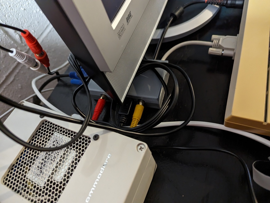
Here are a few pictures of the Commodore 128 setup. It is a bit crowded with projects, most of them have posts here on the blog. The Commodore 64 replacement Power Supply, a Commodore 64 to Commodore 128 Power Supply Adapter cable (I don’t have post about it, It takes the C64 power jack on once side and the Commodore 128 plug is from “Hey Birt!“. My C64 power supplies were built for higher current than the factory model making them able to handle the C128’s requirement fine. I used Drunk “n” Retro’s Diagram, which you can find many examples of diagrams to do so ). I do have the serviced Commodore 128 Power Supply, but it is easier to just swap in the adapter cable, than having both out on the desk. The Commodore 128 is connected to the Samsung 940MW TV I repaired. I of course have the RGBI Adapter tucked in under the monitor. I do have the Monochrome Composite 80 column connected up to the TV, as I was testing it. I also have the 40 Column SVideo connected to the TV. The RGBI Adapter is connected across to the GBS Control (silver box on the right under the pi1541 which is another project). Then the Commodore 128 which I serviced, but I guess I have no post on servicing it. I’m still debating painting it, I won’t be retrobrighting it.
Finally the gamepad project, which I don’t have a post about. It is far from flawless, the Dpad isn’t great. It has 2 buttons, the normal fire button on the left and “button 2” is either “Up” or wired to one of the Pot inputs. It also has an adjustable speed 555 based Rapid Fire option for the primary Fire button. I want to revisit that project, maybe then I’ll make a post about it.


I made up some labels for the two units I built up. Below you will see the original 2019 prototype with the new 2023 label. I made that label the same way as before. It was printed on plain inkjet paper. Then covered with adhesive laminate film and cut to size. In 2019 I masked off the “case” and sprayed adhesive spray onto the case. I then removed the masking and put the label on it. This time I tried the “easy way” of spraying the paper, as you can see it ended up with the obvious effect of the paper looking like it got something on it showing through. That is why I had originally sprayed the Case instead of the label. This was for testing, and I wasn’t completely happy with the label. I need to get new ink cartridges for my printer and then I may remake the label. The second picture shows the reduced build CGA Adapter’s label. This label was printed on a scrap of HP Adhesive Vinyl. The printer didn’t print quite right due to being out of black ink and the red cutting out too. This label does look better overall although it isn’t perfect. I did put a label for Audio In on the CGA label. It is possible to jumper across the outer two pins of the Audio Out jumper to send the “Audio Output” jack to the “Audio In” Pin on the HD15 port for use with the SCART to HDMI Adapter. All I would have to do is open the case and cut in a hole for the rca jack and install it to the board in the future if I wanted to. I don’t plan to do that currently though.

I think that pretty much wraps up this project. You can see the label on the box there now, and the 128 is running JiffyDOS now. I do have the SID Audio, Monochrome 80 Column Composite, 40 Column SVideo, and of course the RGB through the GBS Control into on the Samsung TV.