I had mentioned the video fix for this board in Part 1, but I don’t believe I went over it beyond mentioning. So here it is, Ray Carlsen recommended resistor change for improved Video. These boards shipped with an incorrect resistor installed in the VIC II area, that reduces the level of the Composite Video output.
https://portcommodore.com/rcarlsen/cbm/c64/SCHEMATICS/326298/early%20board%20weak%20video.txt
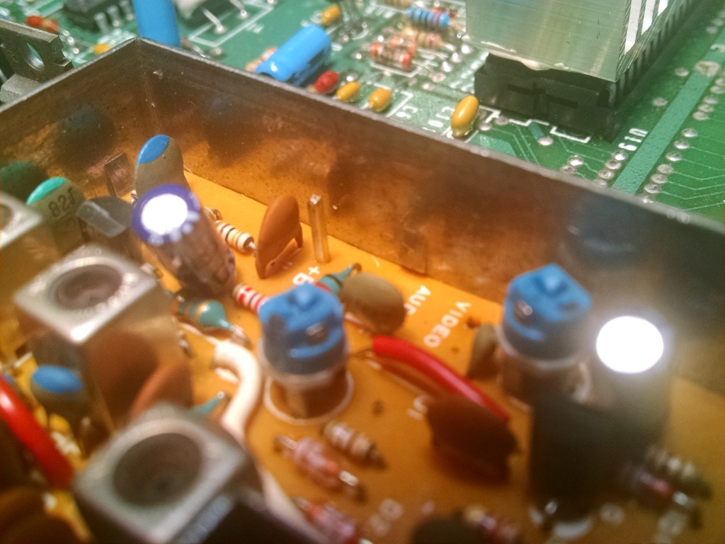
The resistor is R10 next to the VIC chip. His recommended fix is to add another resistor across the factory installed one. By doing this with the right value of resistor, you can get it set to the proper value. It is easier and safer to pull the resistor and replace it. Anytime you desolder a component you risk damage to the rather delicate circuit board traces. It can be done to look very neat as well.

You should be able to see the “stacked’ blue resistor overtop of the factory installed R10. This combination reduces the value to what it should have been. That did noticeably improve the video output. The factory resistor is 300 Ohms, the resistor that should be there is 120 Ohms. So obviously the signal is reduced. When putting a 220 Ohm resistor across the 300 that takes the value of the two resistors together to to give you around 127 Ohms, so that should be plenty close to the 120 that should be there.
So I managed to replace all of the electrolytic capacitors this C64. The Modulator was quite a pain this time around. Also due to that, I let my desoldering iron sit on idle hot for too long. The tip on it started to break down, so I will have to get a replacement. It worked well enough to finish the job though.
I know some people say replace the capacitors, some people say don’t mess with them if it is working correctly.
I say I hate desoldering the RF Modulator, but as far as something causing something I may see, if the modulator caps are going bad that will affect the video output. The RF Modulator is tied in and affects the Composite output as well, as it usually passes through the modulator. It turns out on this revision though the Composite does not go through the modulator, so it seems on this revision you can possibly just remove the modulator. I haven’t verified that though, and don’t intend to try it at this point.


Above I have prepped to work on the capacitors. They are there, as well as my iron and desoldering iron, and solder collection can that I expel the solder into from the desoldering iron.
As I said the modulator was a pain. They had not “turned” the ears on the modulator to hold it in, they had bent over the small pins. I had to work the modulator loose by getting what I could off and putting pressure on the tab I had loose and hold it down while it cooled, then work my way around. I also ended up pulling the 3 square pins up out through the modulator top. That was my best bet to not lift traces. By heating them with my soldering iron from the top side inside the modulator, until it could put pulled up with my pliers that I was holding the pin with. Once they were out of the way, it was one of those pieces they bent over that was stuck in the end making it so I could remove it. I did loose some of the bottom pads, or do a good bit of damage to them where they can is soldered in with the tabs. In the end it doesn’t look too bad, the one that fell off I put back in place and reapplied solder. The one square pin lost the narrow pad from the bottom, but not the through hole thankfully. It was the audio pin and that is why I decided to just heat and remove them pulling them up out. It was a good idea. They are a tight fit, so once I had them out, I ended up using a small file to file off the old solder so they would fit again. You don’t want them loose, because they are double soldered, you risk the solder loosing contact then.
After getting the modulator off, I replaced the capacitors in it, then went and replaced the remaining ones on the mainboard before reinstalling it.


I cleaned the tabs and such on the modulator body and the holes in the board to make sure it would fit back in easily. After that I reinstalled the cleaned up pins into the modulator. In the picture the center one had some solder on it again as I had started to reinstall it but pulled it back off.

I actually pulled it off, so I could check where the traces went under it, for those three pins. I wanted to be able to make sure they were making good contact before finalizing the work. So I reinstalled it, but I did not solder any of the tabs back tight before testing.


She still worked after the replacements. I haven’t tested the Keyboard or Sound though yet. Yes I was wearing an ESD Wrist Strap and working on my grounded ESD Mat.

After it tested good, I then twisted the tabs on the modulator and soldered all of that back on. I did a bit of cleanup of the flux and reinstalled it into the bottom case. Now I need to do that keyboard work so I can put this all back together and use it again.


Here is my desoldering tip. I have seen this happen with Copper based tips, I guess this is Brass looking? If the hot solder is left on them it starts to dissolve the metal of the tip into the solder. It is replaceable, and I like the iron so ordered in a replacement for it. Once they start doing that they keep breaking down. Other types of tips will just burn the plating off and then will quit accepting solder and not transfer the heat properly. I will not leave it idle like that while it is on again. It was while I was working with the modulator, which may have taken a hour. I was taking care to not wreck it, so it took awhile.
Beyond the modulator it was an easy recap. Most of the capacitors I pulled tested pretty reasonable but not all.
Three of the 10uF capacitors tested with almost no capacitance. Otherwise they were a little inconsistent and all of them measured above their stated values. The new ones are closer to their rated values. With those three odd ones, I feel it was worth it.
Well on to revisit the keyboard. I really don’t want to take it apart again, but the * key is kind of important. So I will get that in the next and likely last post on this refurbishment.
