I have been wanting to get a working display for the Commodore 128 80 Column mode. Looking into it, certainly get an old compatible CRT Monitor, either a Commodore RGBI monitor or apparently a CGA monitor potentially. Well they are old and they are expensive, and quite expensive to ship. There a couple more modern LCDs, including some NEC Multisync 70 series monitors. They are apparently around, but they are old and somewhat expensive too. If I get a display I would rather have confidence that it will last for a fair while. That and I am pretty cheap I guess.
I looked at options, the Monochrome Composite 80 Column mode is easy. Just make up a cable with the DB9 and a regular RCA plug on the other end. I want color though.
There are some CGA(RGBI) to VGA converters that people make to sell. They convert the Digital CGA signal to an Analog RGB signal, that is close to VGA. The frequency is at the CGA 15khz though instead of 31khz like VGA though. So most monitors don’t accept the 15khz signals (NEC Multisync 70 series is one of the few again, and the 60 series that I have doesn’t). Then you need a second unit that then takes that 15khz to a 31khz VGA signal.
I found a circuit design for a CGA/RGBI to Analog VGA. This is the first part, and you need a secondary converter to take the 15khz signal to the standard VGA 31khz. The GBS-8200 is a popular solution to take the signal to 15khz. I found another solution, which is a SCART to HDMI converter that Adrian Black posted about on his Youtube channel. I picked one up, an a donor cable to make up a proper cable for it.
I took the RGBI converter diagram and came up with a bit of a hybrid of it. I had tried an earlier wiring up to see if my Multisync 60 series monitor worked, it didn’t. So I am making up up circuit I found. There was a report by another site that said they didn’t like that circuit, and preferred another circuit for the process.
The draw back of these RGBI converters is that while they are full 16color output, they output Dark Yellow in place of Brown. It is not a fault of the circuit, it is because that is how CGA/RGBI worked, the Monitors actually handled the color replacement. To do the Dark Yellow to Brown replacement requires including the 74LS138N ic. When it gets the “Dark Yellow” signal, it injects just a little bit into the “Green” pushing the visual output from Dark Yellow to Brown through R1 below.
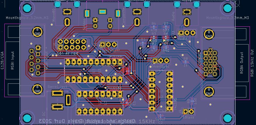
Update 2/5/23: Today I was looking to revise this project to a PCB Design. In looking at, it I and thought the Sync Invert was incorrect on the schematic. I was wrong, it was correct so I have switched the schematic back to the original from 2019. I have no promise I will complete a PCB design, but if I do I will be posting it up on Github or another site. I am thinking of making the pcb to fit into the same case I used for the prototype if possible. To make it more useful for IBM CGA I plan to put a power jack on it, the Commodore AV Port will be a pin header row or something, so it will be optional. There will be the optional Audio Jack coming from the Commodore AV Port, as well as an option for the Monochrome 80 Column Composite output (because I can), Commodore 40 Column Composite as well as Commodore 40 Column SVideo output. I am making the PCB Design in KiCad at this point. I want to see how that works. I had used Eagle back at the time of making this project initially. I have recently used EasyEDA as part of the Super Game Boy project, as Joe had build it in there. I wanted to see how KiCad compares. The schematic is nearly finished in KiCad, but the one in Eagle as seen below looks “neater”. I am finding some issues with KiCad not having footprints I would like to be ready to use, but we will see once I start having to work them out and find parts.
https://hobbytronics.home.blog/2023/03/12/commodore-128-rgbi-cga-to-analog-rgb-part-4-a-new-case/

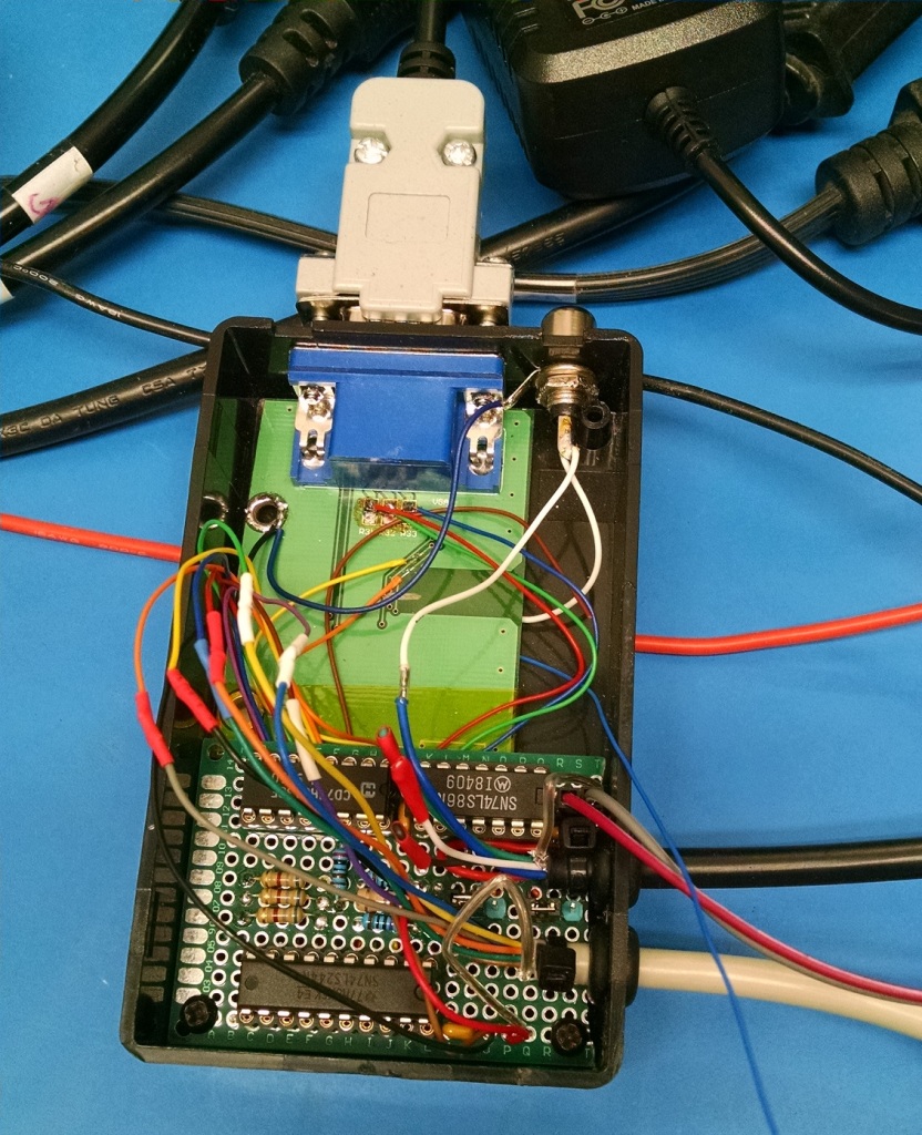
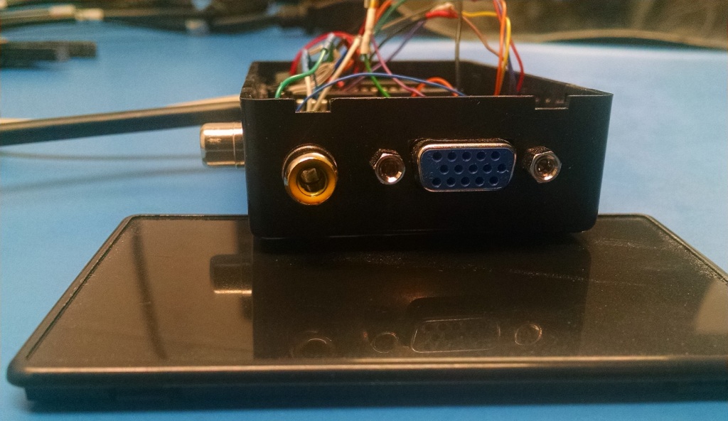
Here are some pictures of the unit built up on some protoboard and reusing a section of board with a HD15 VGA connector on it. There are a couple of things I will be doing with the board, first I will be installing a 150 Ohm resistor on the board (R9). Currently in the second picture you can see an old 150 Ohm resistor in there for testing. I was making sure that 150 Ohms wasn’t too much and that it brings the current usage down to what I consider should be a safer level. Initially I had been using a higher value resistor and the circuit wouldn’t work. The SCART box needs enough voltage on Pin16 “Blanking” which switches it over from Composite Video to RGB Video mode. With too low a resistor I wasn’t happy with the current draw. I am going to be powering this board from the Commodore 128’s AV Port. I didn’t want to risk damaging the computer by pulling to much power through the port. With the 150 Ohm it had lowered it to a better level. The other changes I will be making also involve the AV Port connector. I want to be able to connect up for both 80 and 40 Column video modes, with the AV Port plugged into the box for power, I can’t get to the 40 Column signals. I am going to add another RCA jack for the Composite Video, I will also add a SVideo port somehow later on, so that will be an option for 40 Column mode. The a RCA port was the Audio out coming in from the AV Port originally when the first pictures were taken (in the end I moved the Audio to the side, and made that port 40 Column Composite Video). The Audio also goes into the “vga” jack and is sent to the SCART converter to go into the HDMI signal from it. I could have hard wired in the SCART Cable instead of including the VGA port. I wanted to give myself other options with the box though. That is also why there are some jumpers on the schematic. They are there on the board, but they are not easy to see as they are a bit under the wires in the pictures below. The jumpers can allow to switch from Combined Sync mode (CSync), to the VGA Split Sync (HSync & VSync). The second Jumper is the Inverter jumper for CSync/HSync line, with it one way the CSync is inverted, with it the other way it is not inverted. This gives options to potentially connect to other devices, like the GBS8200, maybe some Multi Sync VGA monitor if I come across one. The only concern I have with either of them, is that I am sending Audio to the VGA port to Pin 4. If the Monitor or the GBS board do anything with Pin4 they could damage the SID or be damaged themselves. The other alteration on the VGA pin out is Pin 9 has the “Blanking” voltage wired into it, old VGA cards (very old I guess) sometimes had a 5Volt output on that pin, so as I am feeding it with something under 5Volts it shouldn’t do anything, but that doesn’t mean something won’t be wired to it. I have seen diagrams of people thinking Pin 9 on the VGA port should be Grounded, which that would be bad.. certainly it wouldn’t be a good thing to do.
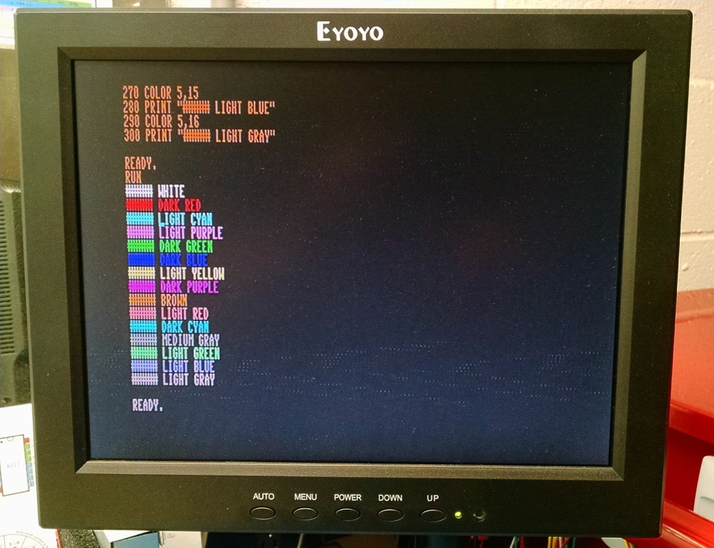
So after a lot of checking of my wiring, I finally connected it up to the Commodore 128, and well it worked. That was great because I couldn’t get it to work 100% on the breadboard. I though the issue might be the variation of the XOR Gate IC I was using, so I had ordered in some replacements, so it was either that or all of the slop of the breadboard wiring. There is that “Saturn’s Rings” looking interference there going across centered around the Light Blue line. That was a visible thing on the display. I didn’t have that specific issue in the breadboard circuit. The point to point wiring isn’t the best either, so maybe that has something to do with it. I have yet to try it on another monitor though. Still I am pretty happy with it, and soon I will be able to close the box up and make use of the 80 Column mode when I want to. The color correction on the Brown seems to be working, the text at the top is in “brown”. At the least I can say it looks closer to Brown than Dark Yellow to me. The other colors look reasonable to me as well.
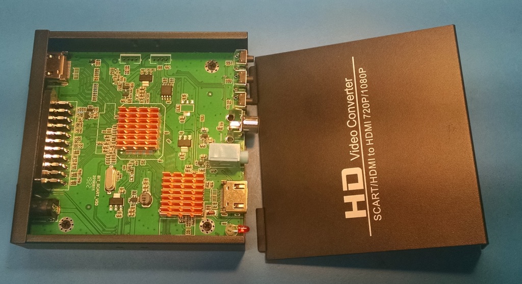
Below here is the SCART to HDMI Converter I am using. I found it on a video by Adrian Black where he was recommending this model specifically over the other similar priced models. He said that Heatsinks needed applied to the two chips inside though.


Below you can see the two heatsinks I installed. I hope they are enough, the little one in the lower right is fine, but the main chip heatsink is smaller than the one Adrian was using. I don’t know how hot these get with use. If they “sort of work” without them, I would hope that they will be just fine with these. They are the type that come with some 3m tape applied.
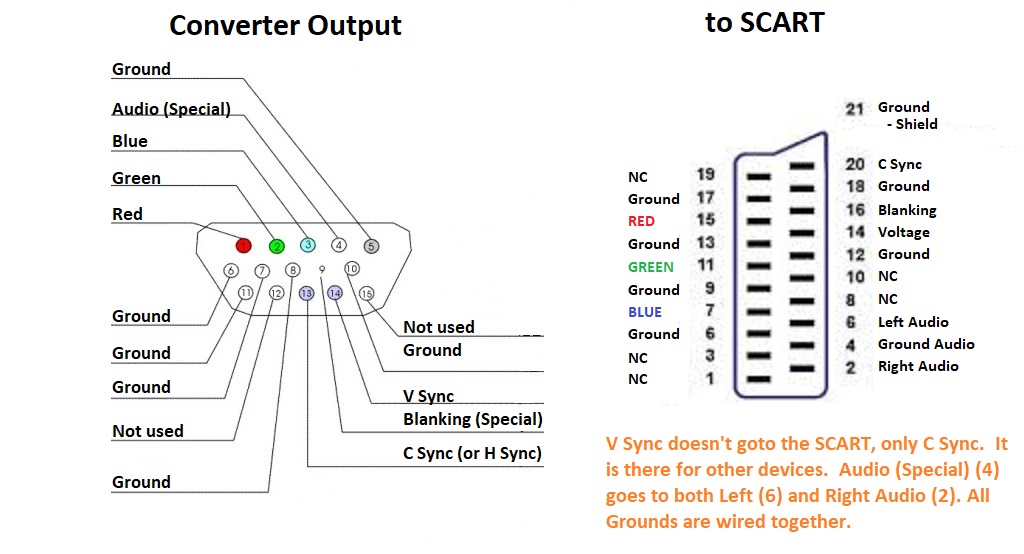
Above I have put together a diagram of the Output of the circuit I built and how it is wired to the VGA port and then how that wires over to the SCART Cable. For a GBS8200 or proper Multi Sync VGA monitor you would just use a regular VGA Cable. I would feel better if you used a minimal VGA cable, which is R,G,B, Ground, C Sync/H Sync and V Sync. I find that the thin modern VGA cables now only have those wires in them. I have had older ones that were about as small but did have all of the wires in them. I am putting in a jumper to disconnect the Audio from the VGA port for safety. When the jumper is moved to the other position the audio then goes to the RCA port on the side (the Red one not the Yellow one).
Commodore AV Port Composite Video (40 column output). I painted it yellow to reflect what it is.


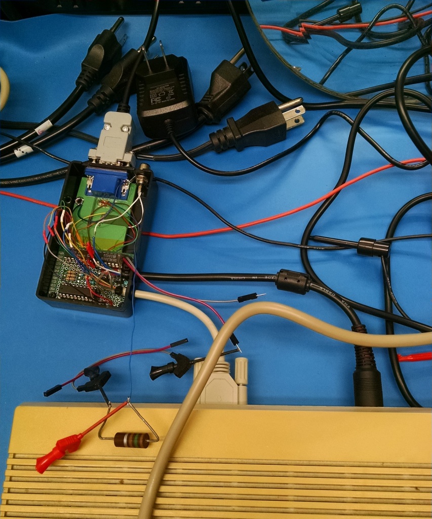
I certainly look forward to using this setup for my Commodore 128. I added the label below, it is printed on an inkjet printer with standard paper. I then used some tape to mask off the top of the box, and sprayed it with Locktite Spray Adhesive 200 Middleweight bonding spray. I let it slightly dry before putting the paper inplace so that it would not bleed into the paper. It is sticking perfectly, I guess I will see how long it holds up. I may have put some clear packing tape over it before cutting it out, but I didn’t have any. I have used the process for some cartridge labels as well.


A few References:
https://sites.google.com/site/h2obsession/CBM/C128/rgbi-to-scart
https://sites.google.com/site/h2obsession/CBM/C128/rgbi-to-vga/ultimate
https://groups.google.com/forum/#!msg/comp.sys.cbm/ARbaCb8n9Sg/B0UPWvrKOaUJ
Nothing above is exactly what I ended up with, but that is what I based my converter off of. I used H2Obesssion’s CSync and SCART info, and then the other for the Digital to Analog and Brown fix. I would really have liked H2Obession’s “Ultimate” circuit to have worked out. There were reasons it did not work in my case, mostly I think it was the SCART Blanking. If I make another, I was thinking of trying it again.
The unit does work for me, it may not startup the Sync signal quickly enough and I have to reset the Commodore 128 to get the display to show.
The design can be adapted for IBM CGA use. The only difference there is the source of the 5Volt power as there is no Commodore AV port to supply it. Certainly a DC power jack could be added instead for a 5Volt DC power input.

Regarding the recent update: You have XOR gates, not Inverters. You need one input tied to 5v in order for a XOR gate to work as an inverter. By tying the two inputs together you will only ever get a Low output.
LikeLike
You are correct. It’s been around 4 years since I had worked on it, and I mistaken yesterday when I as going over the schematics. I have already put back the original 2019 schematic wired with the input to 5V. I may have been looking at the wrong datasheet or a bad datasheet, I don’t know.
LikeLike